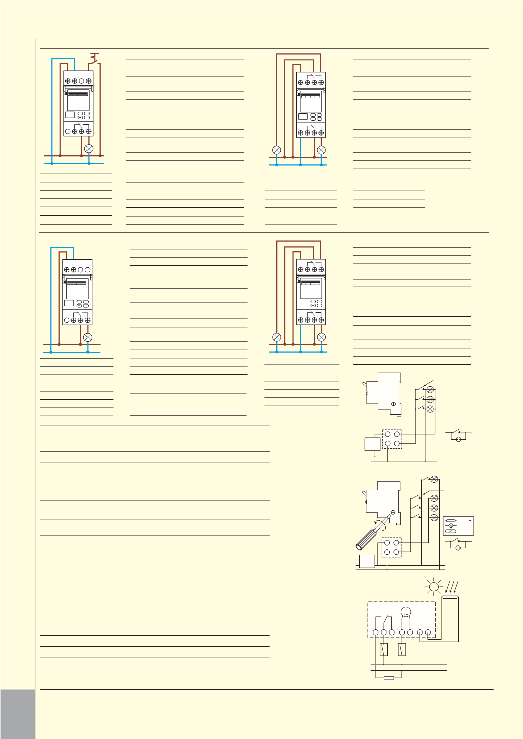

CONTROL MODULES – GENERAL
l
P
MCB
16A
max
3
N 4
L1 (P)
N
Retractive switches
Timed lights
Switch with neon
3
P
MCB
16A
max
3
N 4
4
L1 (P)
N
Retractive switches
Timed lights
Switch with neon
Normal lighting
16/240
2000W
2000W
1 2 3
4 5
L N
M
LOAD
N
L
SENSOR
Staircase 3 wire
Typical wiring diagram
Staircase 4 wire
Typical wiring diagram
STAIRCASE TIME SWITCH
l
Operating voltage 190–240V
Mains frequency 50–60Hz
Switching capacity 16A resistive, 2000W tungsten, 2000W fluorescent
Connection: 3-lead rising mains
4-lead rising mains
Timed, reswitchable Timed, reswitchable lighting.
lighting.
Untimed, standard lighting switches.
Synchronous motor.
Time range 1–7 minutes.
Glow lamp max 50mA.
Override switch for permanent ‘on’.
Pre-selector switch for 3-4 wire connection.
Twilight switch
Typical wiring diagram
TWILIGHT SWITCH
l
Operating voltage
190–240V
Mains frequency
45–60Hz
Power consumption
2.2VA
Contact rating resistive @ 240V 10A
Incandescent lamp load
1000W
Brightness range
2–2000 lux
Switching delay (on/off)
80 seconds approx
Switching status indication
LED (no delay)
Connection cable for light sensor 2 core cable max length 100m
Permissible ambient temp
-10 to +50°C -40 to +70°C
Protection category
IP20 IP54
Can be wired normally open or closed.
Delay ‘on/off’ eliminates nuisance switching.
Selector switch for adjustment of ranges: range 1 2–35 lux; range 2 35–2000 lux.
Connection of additional timing device will provide facility to override ‘switch on’ status.
control
unit
control
unit
light
sensor
L
S N
1
7
OK
MENU
+
S SIGNAL
AUTO ON
TUE 14 : 00
02 .
.
NOV 2010
L
N
L
1
N
1
7
C1 C2
2
OK
MENU
+
KANAL 1
AUTO EIN
TUE 14 : 00
02 .
.
NOV 2010
L
N
L N
1
7
OK
MENU
+
AUTO ON
TUE 14 : 00
02 .
.
NOV 2010
L
N
L
1
N
1
7
C1 C2
2
OK
MENU
+
CHANNEL 1
AUTO ON
TUE 14 : 00
02 .
.
NOV 2010
L
N
Resistive Loads
3600W
Incandescent/Halogen 1800W
E S/L V Fluorescent
100W
Motors
1800W
Mains Halogen
1800W
L V Halogen
2300W
Resistive Loads
3600W
Incandescent/Halogen 1800W
E S/L V Fluorescent
100W
Motors
1800W
Mains Halogen
1800W
L V Halogen
2300W
Incandescent/Halogen 1800W
Mains Halogen
1800W
L V Halogen
2300W
E S Lamps
100W
L V Fluorescent
100W
Motors
1800W
Fluorescent
2300W
Incandescent/Halogen 1800W
Mains Halogen
1800W
L V Halogen
2300W
E S Lamps
100W
L V Fluorescent
100W
Motors
1800W
Fluorescent
2300W
502/TD1
Technical Details
Supply Voltage
230V 50/60Hz
Power Consumption ca.1W
Relay Output
1 changeover contact 16A
250V~
cos
=1
Parallel compensation 60VA max. 7 F
Accuracy
±0.2 s/day under typical
installation conditions
Wire cross-section Single strand 1.5 - 4mm
2
Multi strand 1.5 - 2.5mm
2
Programs
28
Geographical
Resolution 1˚
co-ordinates
Control Cable length Max. 20m
Control Signal
230VAC/ca.2mA
120VAC/ca.2mA
24VAC/ca.2ma
Control-pulse duration
> 100ms
Delay time
0 min-23h 59 min
Battery Reserve
6 Years
Storage Temp.
-20˚C to +60˚C
Operating Temp.
-20˚C to +55˚C
402/TD1
Technical Details
Supply Voltage
230V 50/60Hz
Power Consumption ca.1W
Contact rating
1 changeover contact 16A
250V~
cos
=1
Parallel compensation 60VA max. 7 F
Accuracy
±0.2 s/day under typical
installation conditions
Terminal capacity
Single strand 1.5 - 4mm
2
Multi strand 1.5 - 2.5mm
2
Programs
56
Pulse start times
84 (only if pulse function is
activated)
Pulse duration
1s-59 min 59 s
Battery Reserve
6 Years
Storage ambient
-20˚C to +60˚C
Operating ambient
-20˚C to +55˚C
502/TD2
Technical Details
Supply Voltage
230V 50/60Hz
Power Consumption ca.1W
Contact rating
2 changeover contact 16A
250V~
cos
=1
Parallel compensation 60VA max. 7 F
Accuracy
±0.2 s/day under typical
installation conditions
Terminal capacity
Single strand 1.5 - 4mm
2
Multi strand 1.5 - 2.5mm
2
Programs
14 per channel
Geographical
Resolution 1˚
co-ordinates
Battery Reserve
6 Years
Storage ambient
-20˚C to +60˚C
Operating ambient
-20˚C to +55˚C
402/TD2
Technical Details
Supply Voltage
230V 50/60Hz
Power Consumption ca.1W
Relay Output
2 changeover contact 16A
250V~
cos
=1
Parallel compensation 60VA max. 7 F
Accuracy
±0.2 s/day under typical
installation conditions
Wire cross-section Single strand 1.5 - 4mm
2
Multi strand 1.5 - 2.5mm
2
Programs
28 per channel
Geographical
Resolution 1˚
co-ordinates
Battery Reserve
6 Years
Storage Temp.
-20˚C to +60˚C
Operating Temp.
-20˚C to +55˚C
System Requirements
USB
Windows 98 (SE), Windows 2000, Windows XP
or Windows Vista
Memory Requirements
Approx 40Mb
186
TECHN I CAL DATA
CONT ROL MODU L E S


