


 180 / 211

180
TECHN I CAL DATA
C I RCU I T P ROT ECT I ON
SPECIFICATION
l
BS EN 61008 RCCBs
EN 61009-1, IEC61009-1 RCBOs
BS 7288 SRCDs
Range of current ratings
13–100A
Range of sensitivities
10–300mA
Pole configurations
SP&N, DP & 4P
DP SRCD – 230V
Voltage ratings
1 & 2 Module SP & N – 230V
2 & 3 Module DP – 230V
4 Module 4P – 400V
Frequency rating
50Hz
Tripping principle employed Electro-mechanical (2, 3 & 4 Module RCCBs)
Electronic (1 & 2 Module RCBOs)
OPERATION
l
The RCD employs the current balance principle which involves the supply
conductors to the load (phase and neutral) being wound onto a common
transformer core to form the primary windings. The secondary winding of the
current transformer is then connected to the trip mechanism, either an electro-
magnetic relay in the case of 2, 3 and 4 module RCCBs or an electronic relay
in the case of 1 and 2 module RCBOs. Under healthy circuit conditions, the
current in the phase conductor is equal to the current in the neutral and the
vector sum of the current is zero. In the event of an earth fault, an amount
of current will flow to earth, creating an out of balance situation in the
transformer assembly. This out of balance is detected by the secondary
winding of the transformer and at a pre-determined level of out of balance
will activate the trip mechanism.
Single phase and neutral or three phase and neutral units (suitable for 3 or 4
wire systems) are available, the latter being suitable for balanced or
unbalanced 3 phase loads.
The RCD trip mechanism will operate at a residual current of between
50–100% of its rated residual operating current (sensitivity).
TEST BUTTON
l
A test button is provided on all RCDs to enable the operation of the device to
be checked.
It is recommended that an RCD is tested at least quarterly. (See BS 7671
Regulation 514-12-2).
RESIDUAL CURRENT DEVICES (RCCBs, RCBOs and SRCDs)
l
TERMINAL CAPACITIES
l
Lifestar RCCBs
50mm
2
Lifestar SRCDs
3 x 2.5mm
2
3 x 4mm
2
2 x 6mm
2
Starbreaker RCBOs 16mm
2
Loadstar RCBOs 16mm
2
APPLICATIONS
l
a) Residual Current Devices (RCDs) may be required to ensure the compliance
of an installation with BS 7671, formerly the IEE Wiring Regulations.
An RCD (30mA) meeting the requirements of Regulation 415.1.1 must be
used for circuits and cable installations covered by Regulation 411.3.3 (socket
outlets), 522.6.6, 522.6.7, 522.6.8 (wiring systems), and 701.411.3.3
(locations containing a bath or shower). Where a high earth fault loop
impedance disqualifies the use of overcurrent protection devices as a means
of providing the necessary automatic disconnection in the case of a fault, an
RCD may be used to satisfy the requirements of Regulation 411.3.2.2
(411.4.9). To comply with Regulation 411.5.3 the earth fault loop
impedance in Ohms multiplied by the rated tripping current of the RCD in
Amperes must not exceed 50(V). With the RCD having a sensitivity of 30mA,
the maximum permissible earth fault loop impedance is calculated as follows:
Z
S
(max)=50/0.03=1666 Ohms
Rated residual
Maximum earth fault loop Impedance
Z
S
Ohms
operating current (mA)
120V<Uo
≤
230
30mA
1667
100mA
500
300mA
167
(b) to provide a higher level of protection than that given by direct
earthing, against fire or shock risks caused by earth leakage currents.
Overcurrent protection devices cannot detect earth fault currents below their
operating current. If they are the only means of earth fault protection, it is
possible for sufficient earth fault current to flow undetected to constitute a
fire risk.
By using an RCD, the flow of the sustained earth fault current, above the
tripping current of the RCD, is prevented. The shock risk associated with these
earth fault currents is also greatly reduced.
To provide complete personnel protection, a high sensitivity RCD to a Type A
classification with a maximum tripping current of 30mA should be used. This
is particularly important with portable appliances where there is a danger of
losing earth continuity due to damage or fatigue.
Residual current devices are completely selective in their operation. They are
unaffected by parallel earth paths and are thus ideally suitable for the
protection of installations in modern high density dwellings or office blocks.
They are virtually tamperproof and provide a predetermined level of
protection. Even if earthing conditions deteriorate substantially, they will
continue to provide a higher level of protection than would have been given
by direct earthing.
SENSITIVITIES
l
10mA
provides the highest degree of personal protection, for use in sensitive
areas such as laboratories, schools and workshops where potential hazards
exist from electrical faults caused through misuse, accidental damage or
failure of electrical appliances.
30mA
provides a high degree of personal protection, satisfying the
requirement of Regulation 415-1 for additional protection. (when an
operating time not exceeding 40ms at 5 times rated residual operating current
is proven.
100mA
provides a high level of fire risk protection and a degree of fault
protection.
300mA
provide fire risk protection.
TRANSIENT EARTH LEAKAGE CURRENTS
l
All Crabtree residual current devices incorporate a high level of immunity
to tripping when subjected to transient earth leakage currents.
Such transients can occur when there is a significant level of capacitance to
earth as can result from cable capacitance (particularly MICC) or RF filter
networks. Crabtree RCDs are therefore less susceptible to nuisance tripping
due to transient earth leakage currents.
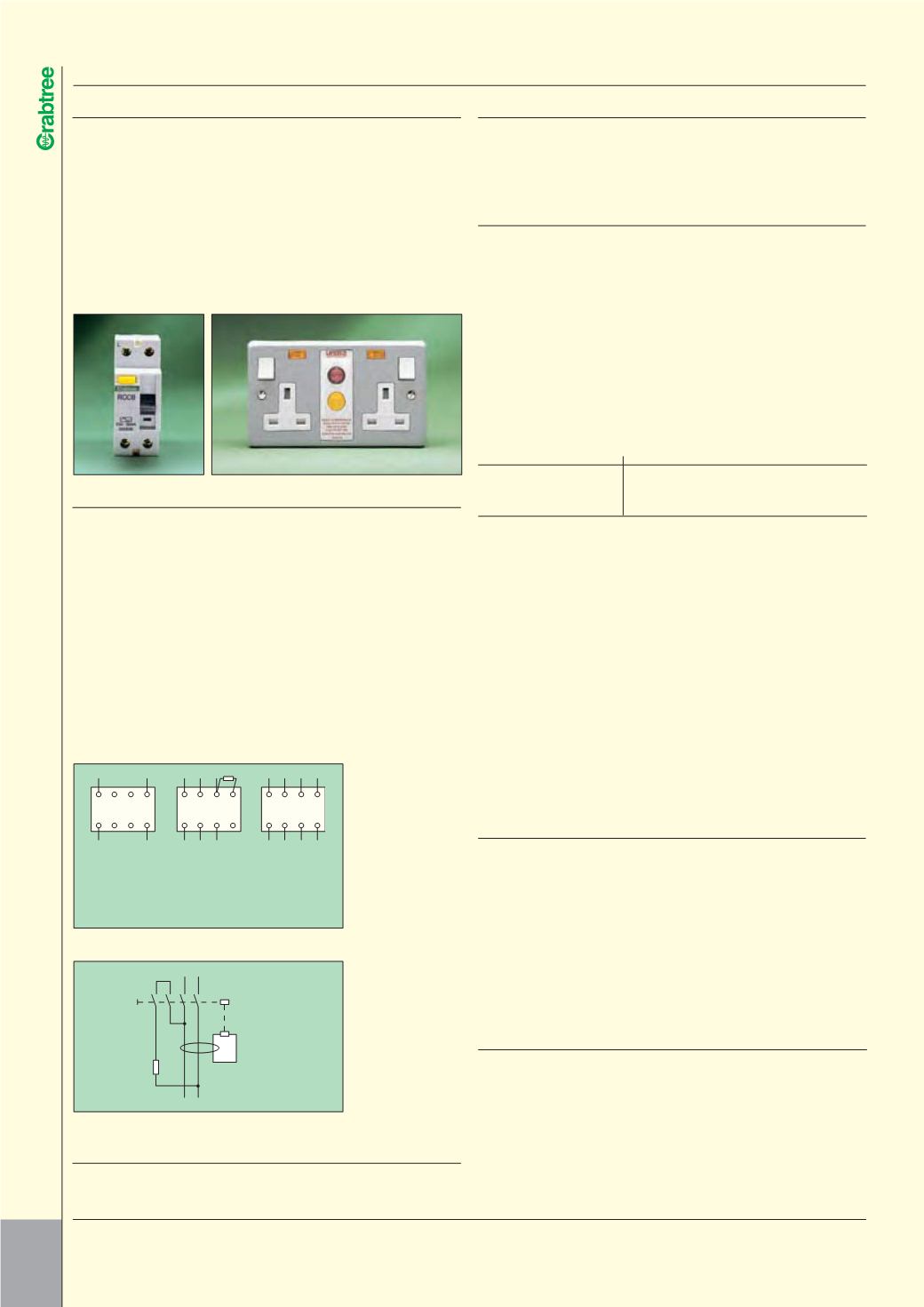
N 5 3 1
L (N)
L (N)
two pole
N (L)
N (L)
N 6 4 2
N 5 3 1
L1 L2 L3
L1 L2 L3
R
three pole
N 6 4 2
N 5 3 1
L1 L2 L3 N
L1 L2 L3
four pole
N 6 4 2
N
RCD circuit diagrams (four pole)
Tripping
Device
Test button
(interlocked)
1/2 3/4
2/1 4/3
Test
resistor
Current balance
transformer
Fault sensing
winding
RCD circuit diagram (two pole)
Note
Exposed installation
metal work must be
earthed.
RCCB in a three-phase system without a neutral conductor:
The N terminal should be connected to terminal 5 or 6 via the R
resistor, depending on the supply side, in order to keep 230V
power supply voltage of the test circuit. Test current is wrong
if the value of the R resistor is incorrect or if only a wire
connection is used instead.
Note
Exposed installation
metal work must be
earthed.