
3 Establishment of arc between fixed and moving contacts
As the moving contact moves away from the fixed contact, an arc is
established. The arc runs along the arc runner to the arc chamber where it is
split up between the plates and extinguished.
The low inertia and consequent high speed of the moving contact has a
limiting effect on the flow of fault current. The rapid development of the arc,
together with its accelerated extinction in the arc chamber, gives a typical
operating time of 3.5–5 milliseconds.
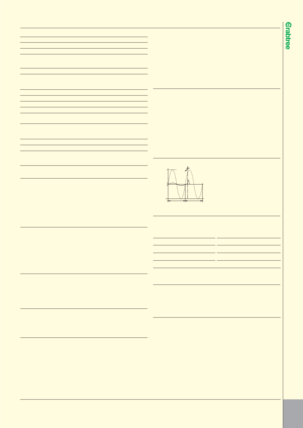
CURRENT LIMITING ACTION
l
The high speed current limiting action ensures that the MCB operates before
the full prospective fault current is allowed to develop.
Under fault conditions, damage can be sustained to the installation and
associated equipment due to the amount of energy that passes before the
current is completely interrupted. The total energy let-through depends on
the value of current and the time for which it flows, and is denoted by the
symbol
I
2
t. The high speed current limiting action of Starbreaker and Loadstar
MCBs ensures that the energy let-through and any subsequent damage is
minimised. This reduced energy let-through assists greatly with both back-up
and discrimination considerations.
CURRENT LIMITING EFFECT
l
I
2
t ENERGY LET-THROUGH
l
Typical values of
I
2
t energy let-through for Starbreaker MCBs are given in the
table below:
MCB rating Total
I
2
t let-through (A
2
s) MCB rating Total
I
2
t let-through (A
2
s)
(A)
Type B
Type C (A)
Type B
Type C
6
10,220
14,890 32
31,760
32,470
10
17,900
18,750 40
31,760
32,470
16
22,260
23,820 50
45,160
44,270
20
22,260
32,470
Prospective short circuit test current 6000A
MOUNTING THE MCB
l
In Crabtree consumer units the MCBs are mounted on standard 35mm top
hat rail to BS 5584: 1978 EN 50022 giving a projection within the Standard of
70mm. Due to the method of connection onto the busbar it is not possible to
use the Starbreaker range for custom built panels.
MAIN SWITCH
l
Starbreaker
100/M
I
2 & 100/2MT
Loadstar (Domestic)
100SW2
Specification
IEC 60947-3
Rating
100A 230V 50Hz
Utilisation category
AC-22A
Type
Double pole switch disconnector
Insulation voltage
250V
Impulse withstand voltage
4kV
Rated duty
Continuous
Short-time withstand current 2kA for 1 second
Short-circuit making capacity 3.5kA (peak)
Conditional short-circuit current 16kA when protected by 100A HRC fuse
to BS 1361
Pollution degree
3
T ECHN I CAL DATA
C I RCU I T P ROT ECT I ON
179
APPLICATIONS
l
Single pole MCBs with Type B characteristics (3-5
I
n) are suited for use on loads
with little or no switching surges, such as occur on domestic applications.
In addition, a Type B MCB will give fault risk protection at higher levels of earth
loop impedance. All ratings are also available in Type C classification (5–10
I
n).
MCBs with type C characteristics are suited for use where fluorescent lighting
circuits, small motors etc. may produce switching surges which would operate
a type B circuit breaker.
GENERAL CONSTRUCTION
l
Starbreaker and Loadstar MCBs are of the thermal-magnetic current limiting
type, having a compact construction which has been achieved by not only
minimising the number of parts but also the number of welded joints and
connections. Critical material selection ensures reliability and durability. The
MCB has an easy to operate handle with a trip-free toggle mechanism – so
even when the handle is held in the ‘on’ position the MCB is free to trip.
BACK-UP PROTECTION
l
Back-up protection is required only if the prospective short circuit current at
the point of installation exceeds the breaking capacity of the MCB. When
providing back-up protection consideration must be given to discrimination
between the MCB and fuse.
DISCRIMINATION
l
It is desirable that the protective device nearest the fault should operate first.
The low energy let through of Starbreaker and Loadstar MCBs provides better
discrimination with HRC fuse back-up than is given by earlier types of MCB.
METHOD OF OPERATION
l
1 Moderate overload conditions
Detection of moderate overload conditions is achieved by the use of a
thermo-metal element which deflects in response to the current passing
through it. The thermo-metal element moves against the trip bar releasing the
trip mechanism.
2 Short circuit conditions
When the current flowing through the MCB reaches a predetermined level,
the solenoid directly pulls in the plunger which forcibly separates the contacts
and simultaneously releases the trip mechanism.
MINIATURE CIRCUIT BREAKERS
l
Maximum
prospective
fault
current
Healthy
circuit
current
Fault
20ms
20ms
Technical Specifications Starbreaker & Loadstar Domestic
Standard
BSEN 60898
Tripping characteristic
B, C
Rated voltages
Un
230/400
Operational voltage
min.
V AC/DC 24
max.
V DC/pole 60
max.
V AC
250
Rated short circuit capacity
Icn
kA AC
6
Insulation coordination
Rated insulation voltage
V AC
250
Degree of pollution for overvoltage category
2/III
Touch protection acc. to EN50274
Yes
Handle end position, sealable
Yes
Degree of protection acc. to EN60529
IP20
CFC silicone-free
Yes
Terminals
Terminal tightening torque
Nm
2.5 ... 3
Conductor cross-section
Solid and stranded
mm
2
0.75 ... 25
Finely stranded, with end sleeve
mm
2
0.75 ... 25
Mounting position
Any
Service life
on average, with rated load
20000 actuations
Ambient temperature
˚C
-25 ...+45, occasionally +55, max.
95% humidity,
Storage temperature: -40 ... +75


