


 27 / 221

27
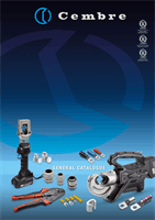
THROUGH CONNECTORS
L-M range of connectors
are designed for jointing
low voltage conductors.
Made of electrolytic Cop-
per tube having the same
dimension as A-M series
lugs: L-M connectors are
annealed and electrolyti-
cally Tin plated.
They feature an internal ta-
per at both ends to ease
the introduction of the con-
ductor and a central stop
to ensure correct position-
ing.
Details of the appropriate
crimping tools and dies
are shown on pages 178
to 179.
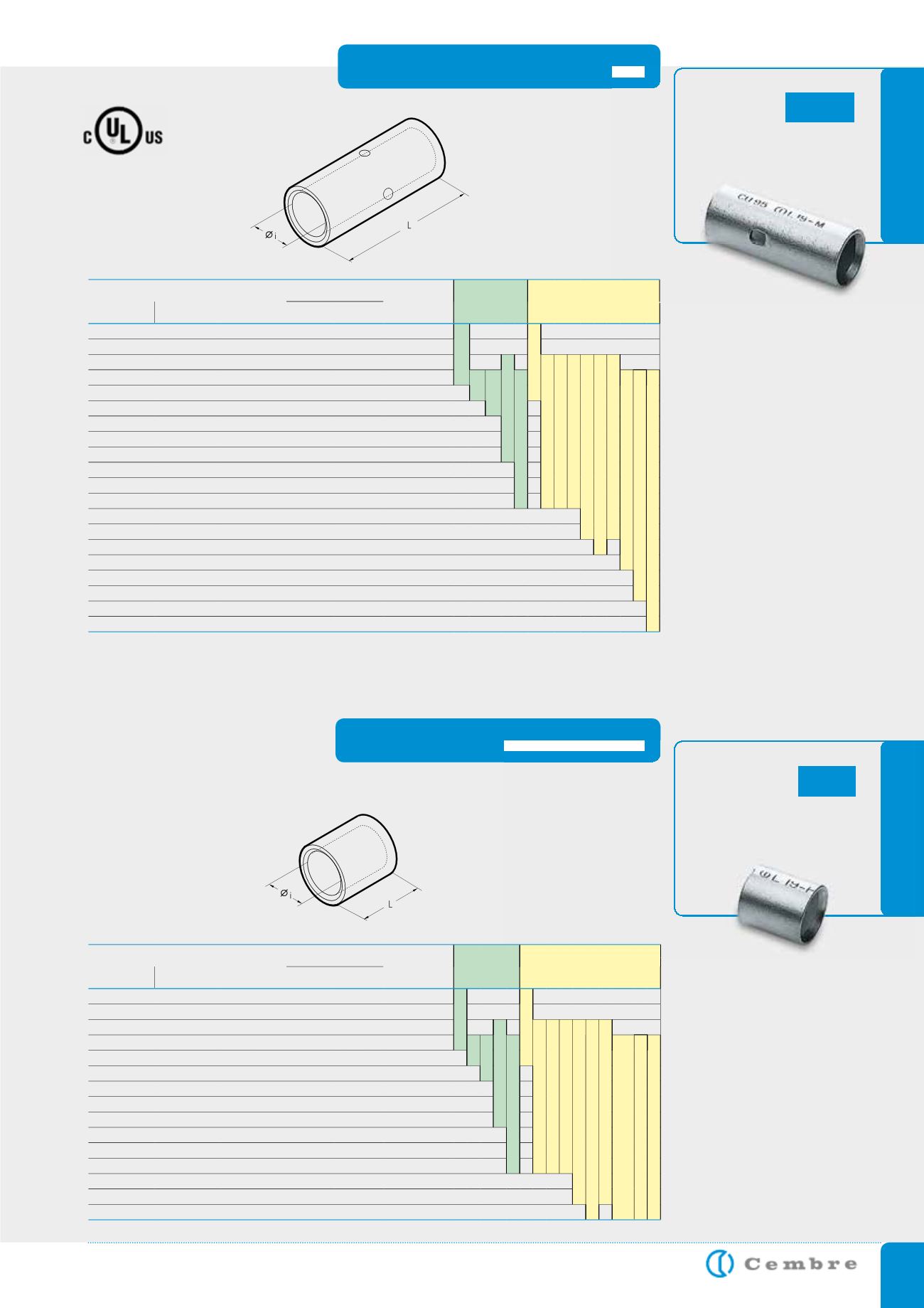
PARALLEL CONNECTORS
Made of electrolytic Cop-
per tube, having the same
dimensions as A-M series
lugs, L-P connectors are
annealed and electrolyti-
cally Tin plated.
They feature an internal
taper to ease the introduc-
tion of the conductor.
Details of the appropriate
crimping tools and dies
are shown on pages 178
to 179.
L-M
L-P
Conductor Size
sqmm
Ref.
D i m e n s i o n s m m
Quantity
Box/Bag
Mechanical
Tools
Hydraulic
Tools
low stranded
Flexible
Ø
i
L
0,25÷1,5 0,25÷1,5
L 03-M
1,8
15
6.000/100
HN 1
B 15MDE
1,5÷2,5 1,5÷2,5
L 06-M
2,4
15
4.000/100
4÷6
4÷6
L 1-M
3,6
22
2.000/100
TN 70 SE
B 35-45MDE
B 35-50MDE
HT 45-E
HT 51 B 550E
RH 50 B 500E
HT 81-U RHU 81
10
10
L 2-M
4,6
25
1.000/100
HN 5
HN-A25
TN 120 SE*
HT 120 and tools and heads with 130 kN crimping force
ECW-H3D
RHU 520
16
16
L 3-M
5,8
27
1.000/100
25
25
L 5-M
7,0
29
500/100
35
25÷35
L 7-M
8,9
33
400/100
50
35÷50
L 10-M
10,0
37
200/50
70
50÷70
L 14-M
11,3
39
200/50
95
70÷95
L 19-M
13,5
43
100/25
120
95÷120
L 24-M
15,2
47
100/25
150
120÷150
L 30-M
16,7
58
50/25
185
150÷185
L 37-M
19,2
64
50/25
240
185÷240
L 48-M
21,1
75
30/15
300
240÷300
L 60-M
23,7
90
20/10
400
300÷400
L 80-M
27,0
94
20/5
500
400÷500
L 100-M
30,3
98
12/1
630
500÷630
L 120-M
33,4
105
12/1
800
600
L 160-M
38,0
112
9/1
1000
800
L 200-M
44,0
120
6/1
Total Conductor Size
sqmm
Ref.
D i m e n s i o n s m m
Quantity
Box/Bag
Mechanical
Tools
Hydraulic
Tools
low stranded
Flexible
Ø
i
L
0,25÷1,5 0,25÷1,5
L 03-P
1,8
6,0
10.000/100
HN 1
B 15MDE
1,5÷2,5 1,5÷2,5
L 06-P
2,4
6,0
5.000/100
4÷6
4÷6
L 1-P
3,6
9,0
3.000/100
TN 7O SE
B 35-45MDE
B 35-50MDE
HT 45-E
HT 51 B 550E
RH 50 B 500E
HT 81-U RHU 81
10
10
L 2-P
4,6 10,5
3.000/100
HN 5
HN-A25
TN 120 SE*
HT 120 and tools and heads with
130 kN crimping force
ECW-H3D
RHU 520
16
16
L 3-P
5,8 11,5
2.000/100
25
25
L 5-P
7,0 13,0
1.500/100
35
25÷35
L 7-P
8,9 14,0
500/100
50
35÷50
L 10-P
10,0 16,0
500/100
70
50÷70
L 14-P
11,3 18,0
500/100
95
70÷95
L 19-P
13,5 19,0
300/50
120
95÷120
L 24-P
15,2 22,0
200/50
150
120÷150
L 30-P
16,7 26,5
100/50
185
150÷185
L 37-P
19,2 26,5
100/50
240
185÷240
L 48-P
21,1 34,0
60/15
300
240÷300
L 60-P
23,7 43,0
50/25
*See page 111
*See page 111
File no. E125401
Not UL approved