


 26 / 221

26
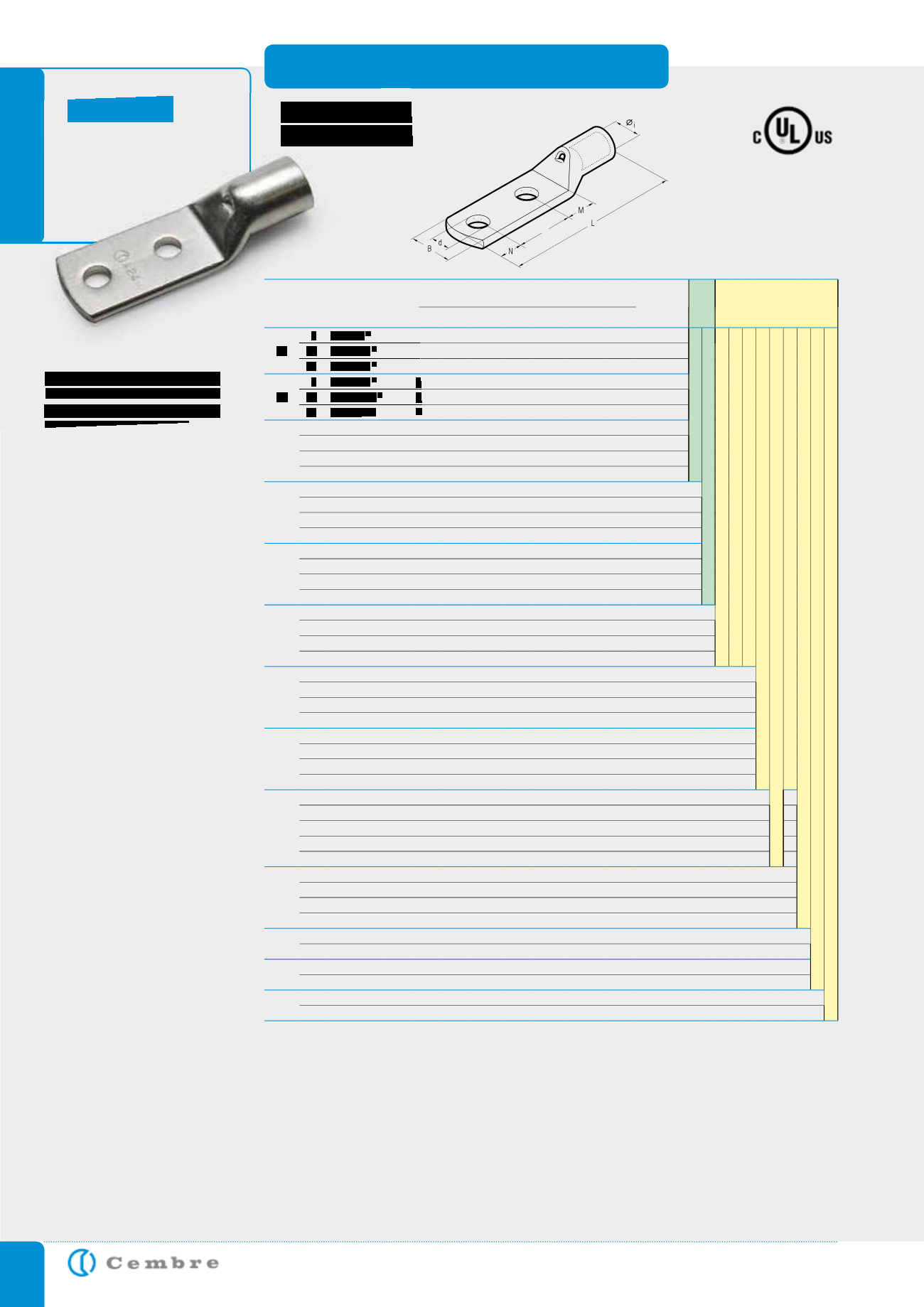
A-2M.. series lugs are
manufactured from elec-
trolytic Copper tube con-
forming to EN13600.
The tube dimensions are
designed to optimise elec-
trical conductivity and me-
chanical strength.
Palms feature double stud
holes at standard 44.5mm
centres.
Other configurations are
available upon request.
Lugs are annealed to en-
sure ductility and satisfac-
tory performance when
subjected to deformation
and vibration.
Inspection holes facilitate
verification of full conduc-
tor insertion, while the
barrel length has been de-
termined to allow easy and
accurate positioning of the
crimping dies.
Lugs are electrolytically Tin
plated to avoid oxidation.
Details of the appropriate
crimping tools and dies
are shown on pages 178
to 179.
COPPER TUBE CRIMPING LUGS
double hole fixing
for Copper conductors
A-2M
E
Cond.
Size
AWG
Ø
Stud
in.
Ref.
D i m e n s i o n s i n.
Quantity
Bag
Mechanical
Tools
Hydraulic
Tools
Ø
i
B M N E
L
d
35
8
A7-2M8
8,9 21,0 13,0 11,0 44,5 90,0 8,4
100
TN 70 SE
TN 120 SE*
B 35-45MDE
B 35-50MDE
HT 45-E
HT 51 B 550E
RH 50 B 500E
HT 81-U RHU 81
HT 120 and tools and heads with 130 kN crimping force
ECW-H3D
RHU 520
10
A7-2M10
8,9 19,0 11,0 10,0 44,5 87,0 10,5
100
12
A7-2M12
8,9 21,0 16,0 14,0 44,5 96,0 13,2
100
50
8
A10-2M8
10,0 19,0 11,0 11,0 44,5 92,0 8,4
50
10
A10-2M10
10,0 20,0 13,0 11,0 44,5 94,0 10,5
50
12
A10-2M12
10,0 21,0 16,0 14,0 44,5 100,0 13,2
50
70
8
A14-2M8
11,3 21,0 11,0 11,0 44,5 95,5 8,4
50
10
A14-2M10
11,3 21,0 13,0 11,0 44,5 97,5 10,5
50
12
A14-2M12
11,3 22,0 16,0 14,0 44,5 103,5 13,2
50
14
A14-2M14
11,3 25,0 18,0 16,0 44,5 107,5 15,0
50
95
10
A19-2M10
13,5 25,0 13,0 11,0 44,5 104,0 10,5
25
12
A19-2M12
13,5 25,0 16,0 14,0 44,5 110,0 13,2
25
14
A19-2M14
13,5 25,0 18,0 16,0 44,5 114,0 15,0
25
16
A19-2M16
13,5 25,0 19,0 17,0 44,5 116,0 17,0
25
120
10
A24-2M10
15,2 28,5 13,0 11,0 44,5 105,5 10,5
25
12
A24-2M12
15,2 28,5 16,0 14,0 44,5 113,0 13,2
25
14
A24-2M14
15,2 28,5 18,0 16,0 44,5 116,5 15,0
25
16
A24-2M16
15,2 28,5 19,0 17,0 44,5 119,0 17,0
25
150
10
A30-2M10
16,7 31,5 13,0 11,0 44,5 113,5 10,5
25
12
A30-2M12
16,7 31,5 16,0 14,0 44,5 119,5 13,2
25
14
A30-2M14
16,7 31,5 18,0 16,0 44,5 123,5 15,0
25
16
A30-2M16
16,7 31,5 19,0 17,0 44,5 125,5 17,0
25
185
10
A37-2M10
19,2 35,5 13,0 11,0 44,5 120,5 10,5
15
12
A37-2M12
19,2 35,5 16,0 14,0 44,5 126,5 13,2
15
14
A37-2M14
19,2 35,5 18,0 16,0 44,5 130,5 15,0
15
16
A37-2M16
19,2 35,5 19,0 17,0 44,5 132,5 17,0
15
240
10
A48-2M10
21,1 39,0 13,0 11,0 44,5 126,5 10,5
15
12
A48-2M12
21,1 39,0 16,0 14,0 44,5 132,5 13,2
15
14
A48-2M14
21,1 39,0 18,0 16,0 44,5 136,5 15,0
15
16
A48-2M16
21,1 39,0 19,0 17,0 44,5 138,5 17,0
15
300
10
A60-2M10
23,7 44,0 13,0 11,0 44,5 133,5 10,5
5
12
A60-2M12
23,7 44,0 20,0 14,0 44,5 143,5 13,2
5
14
A60-2M14
23,7 44,0 22,0 16,0 44,5 147,5 15,0
5
16
A60-2M16
23,7 44,0 22,0 17,0 44,5 148,5 17,0
5
16
A60-2M16/36
23,7 36,0 22,0 17,0 44,5 148,5 17,0
5
400
12
A80-2M12
27,0 51,0 22,0 14,0 44,5 152,5 13,2
5
14
A80-2M14
27,0 51,0 22,0 16,0 44,5 154,5 15,0
5
16
A80-2M16
27,0 51,0 22,0 19,0 44,5 157,5 17,0
5
16
A80-2M16/41
27,0 41,0 22,0 19,0 44,5 157,5 17,0
5
500
12
A100-2M12
30,3 56,5 17,0 14,0 44,5 151,5 13,2
5
16
A100-2M16
30,3 56,5 19,0 19,0 44,5 158,5 17,0
5
630
12
A120-2M12
33,4 61,6 22,0 14,0 44,5 167,5 13,2
1
16
A120-2M16
33,4 61,6 22,0 19,0 44,5 172,5 17,0
1
800
12
A160-2M12
38,0 72,0 20,0 14,0 44,5 176,5 13,2
1
16
A160-2M16
38,0 72,0 22,0 19,0 44,5 183,5 17,0
1
File no. E125401
Not UL approved
*See page 111