
25
A-L
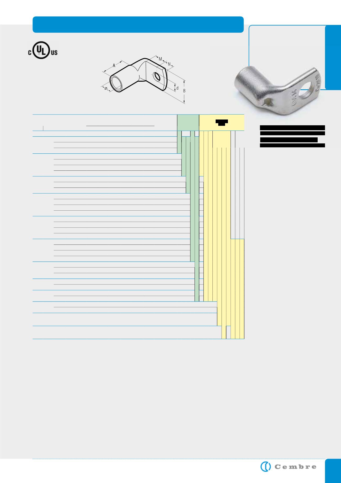
COPPER TUBE CRIMPING LUGS ANGLED 90°
for Copper conductors
A-L series lugs angled 90°
are manufactured from
electrolytic Copper tube.
The dimensions of the tube
are designed to obtain the
most efficient electrical
conductivity and mechani-
cal strength to resist vibra-
tion and pull out.
Cembre lugs are annealed
to guarantee optimum duc-
tility which is an absolute
necessity for connectors
which will have to withstand
the severe deformation
arising when compressed
and any bending of the palm
during installation.
In applications subject to vi-
bration, terminals still have
to perform a reliable con-
nection, annealing plays a
vital role in avoiding crack-
ing or breaks between the
barrel and palm.
The presence of an inspec-
tion hole facilitates full inser-
tion of the conductor, whilst
the barrel length has been
designed to allow easy and
accurate positioning of the
dies during the crimping op-
eration.
Lugs are electrolytically tin-
plated to avoid oxidation.
Details of the appropriate
crimping tools and dies
are shown on pages 178
to 179.
Cond. Size
sqmm
Ø
Stud
mm
Ref.
D i m e n s i o n s m m
Quantity
Box/Bag
Mechanical
Tools
Hydraulic
Tools
low
stranded flexible*
Øi
B M N A d
6
6
A 1-L 6
3,6 11,0 7,0 6,0 9,5 6,4
2.000/100
HN1
TN 70 SE
B 15MDE
B 35-45MDE
B 35-50MDE
HT 45-E
HT 51 B 550E
RH 50 B 500E
HT 81-U RHU 81
10
5
A 2-L 5
4,6 10,0 6,5 6,0 10,5 5,3
1.500/100
HN5
HN-A25
TN 120 SE**
6
A 2-L 6
4,6 11,0 7,0 6,0 10,5 6,4
1.500/100
8
A 2-L 8
4,6 15,0 9,0 8,0 10,5 8,4
500/100
16
5
A 3-L 5
5,8 11,5 6,5 6,0 12,0 5,3
1.000/100
6
A 3-L 6
5,8 11,5 7,0 6,0 12,0 6,4
1.000/100
8
A 3-L 8
5,8 15,0 9,0 8,0 12,0 8,4
1.000/100
10
A 3-L 10
5,8 18,0 11,0 10,0 12,0 10,5
500/100
25
6
A 5-L 6
7,0 14,0 7,0 6,0 13,0 6,4
500/100
8
A 5-L 8
7,0 15,0 9,0 8,0 13,0 8,4
500/100
10
A 5-L 10
7,0 18,0 11,0 10,0 13,0 10,5
500/100
35 25
35
6
A 7-L 6
8,9 17,0 7.0 6,0 15,5 6,4
500/100
8
A 7-L 8
8,9 17,0 9,0 8,0 15,5 8,4
300/100
10
A 7-L 10
8,9 19,0 11,0 10,0 15,5 10,5
400/100
12
A 7-L 12
8,9 21,0 14,0 12,0 15,5 13,2
300/100
50 35
50
6
A 10-L 6
10,0 19,0 8,0 7,0 16,5 6,4
300/100
8
A 10-L 8
10,0 19,0 9,0 8,0 16,5 8,4
300/100
10
A 10-L 10
10,0 20,0 11,5 9,5 16,5 10,5
200/50
12
A 10-L 12
10,0 21,0 12,0 12,0 16,5 13,2
200/50
70 50
70
8
A 14-L 8
11,3 21,0 9,0 8,0 20,0 8,4
200/50
HT 120 and tools and heads with 130 kN crimping force
ECW-H3D
RHU 520
10
A 14-L 10
11,3 21,0 11,0 10,0 20,0 10,5
200/50
12
A 14-L 12
11,3 22,0 14,0 12,0 20,0 13,2
150/50
16
A 14-L 16
11,3 26,0 18,0 16,0 20,0 17,0
150/50
95 70
95
8
A 19-L 8
13,5 25,0 9,0 8,0 24,5 8,4
100/25
10
A 19-L 10
13,5 25,0 11,0 10,0 24,5 10,5
100/25
12
A 19-L 12
13,5 25,0 14,0 12,0 24,5 13,2
100/25
120 95
120
10
A 24-L 10
15,2 28,5 11,0 10,0 25,5 10,5
50/25
12
A 24-L 12
15,2 28,5 14,0 12,0 25,5 13,2
50/25
150 120
150
10
A 30-L 10
16,7 31,5 13,0 11,0 28,5 10,5
50/25
12
A 30-L 12
16,7 31,5 16,0 14,0 28,5 13,2
50/25
185 150
185
10
A 37-L 10
19,2 35,5 13,0 11,0 31,5 10,5
50/25
12
A 37-L 12
19,2 35,5 16,0 14,0 31,5 13,2
50/25
240 185
240 12
A 48-L 12
21,1 39,0 16,0 14,0 33,0 13,2
30/15
300 240
300 12
A 60-L 12
23,7 44,0 20,0 14,0 42,0 13,2
20/10
*Actual conductor section may require a larger lug eg for 120mm
2
size use A30-... lug.
**See page 111
File no. E125401
Not UL approved


