


 23 / 221

23
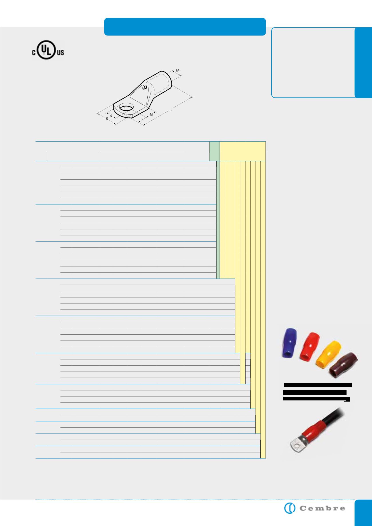
COPPER TUBE CRIMPING LUGS
for Copper conductors
*Actual conductor section may require a larger lug eg for 120mm
2
size use A30-... lug.
A-M
**See page 111
Cond. Size
sqmm
Ø
Stud
mm
Ref.
D i m e n s i o n s m m
Quantity
Box/Bag
Mechanical
Tools
Hydraulic
Tools
low
stranded flexible*
Ø
i
B
M N L
d
95
70
95
6
A 19-M 6
13,5 25,0 8,0 7,0 50,5 6,4
100/25
TN 120 SE**
B 35-45MDE
B 35-50MDE
HT 45-E
HT 51 B 550E
RH 50 B 500E
HT 81-U RHU 81
HT 120 and tools and heads with 130 kN crimping force
ECW-H3D
RHU 520
8
A 19-M 8
13,5 25,0 9,0 8,0 52,5 8,4
100/25
10
A 19-M 10
13,5 25,0 11,0 10,0 56,5 10,5
100/25
12
A 19-M 12
13,5 25,0 14,0 12,0 61,5 13,2
100/25
14
A 19-M 14
13,5 25,0 16,0 14,0 65,5 15,0
100/25
16
A 19-M 16
13,5 27,0 18,0 16,0 69,5 17,0
100/25
20
A 19-M 20
13,5 29,5 22,0 20,0 77,5 21,0
50/25
120 95
120
8
A 24-M 8
15,2 28,5 9,0 8,0 54,0 8,4
100/25
10
A 24-M 10
15,2 28,5 11,0 10,0 58,0 10,5
100/25
12
A 24-M 12
15,2 28,5 14,0 12,0 63,0 13,2
100/25
14
A 24-M 14
15,2 28,5 16,0 14,0 67,0 15,0
50/25
16
A 24-M 16
15,2 28,5 18,0 16,0 71,0 17,0
50/25
20
A 24-M 20
15,2 30,0 22,0 20,0 79,0 21,0
50/25
150 120
150
8
A 30-M 8
16,7 31,5 13,0 11,0 69,0 8,4
50/25
10
A 30-M 10
16,7 31,5 13,0 11,0 69,0 10,5
50/25
12
A 30-M 12
16,7 31,5 16,0 14,0 75,0 13,2
50/25
14
A 30-M 14
16,7 31,5 18,0 16,0 79,0 15,0
50/25
16
A 30-M 16
16,7 31,5 19,0 17,0 81,0 17,0
50/25
20
A 30-M 20
16,7 31,5 22,0 20,0 87,0 21,0
50/25
185 150
185
8
A 37-M 8
19,2 35,5 13,0 11,0 76,0 8,4
50/25
10
A 37-M 10
19,2 35,5 13,0 11,0 76,0 10,5
40/20
12
A 37-M 12
19,2 35,5 16,0 14,0 82,0 13,2
40/20
14
A 37-M 14
19,2 35,5 18,0 16,0 86,0 15,0
30/15
16
A 37-M 16
19,2 35,5 19,0 17,0 88,0 17,0
30/15
20
A 37-M 20
19,2 35,5 22,0 20,0 94,0 21,0
30/15
240 185
240
8
A 48-M 8
21,1 39,0 13,0 11,0 77,5 8,4
30/15
10
A 48-M 10
21,1 39,0 13,0 11,0 77,5 10,5
30/15
12
A 48-M 12
21,1 39,0 14,0 12,0 79,5 13,2
30/15
14
A 48-M 14
21,1 39,0 18,0 16,0 92,0 15,0
30/15
16
A 48-M 16
21,1 39,0 19,0 17,0 94,0 17,0
30/15
20
A 48-M 20
21,1 39,0 22,0 20,0 100,0 21,0
30/15
300 240
300
10
A 60-M 10
23,7 44,0 20,0 11,0 96,0 10,5
20/10
12
A 60-M 12
23,7 44,0 20,0 14,0 99,0 13,2
20/10
14
A 60-M 14
23,7 44,0 22,0 16,0 103,0 15,0
20/10
16
A 60-M 16
23,7 44,0 22,0 19,0 106,0 17,0
20/10
20
A 60-M 20
23,7 44,0 24,0 23,0 112,0 21,0
20/10
400 300
400
12
A 80-M 12
27,0 51,0 22,0 19,0 113,0 13,2
20/5
14
A 80-M 14
27,0 51,0 22,0 19,0 113,0 15,0
15/5
16
A 80-M 16
27,0 51,0 22,0 19,0 113,0 17,0
15/5
20
A 80-M 20
27,0 51,0 24,0 23,0 119,0 21,0
15/5
500 400
500
16
A 100-M 16
30,3 56,5 22,0 19,0 117,0 17,0
15/1
20
A 100-M 20
30,3 56,5 24,0 23,0 123,0 21,0
15/1
630 500
630
16
A 120-M 16
33,4 61,6 22,0 19,0 128,0 17,0
12/1
20
A 120-M 20
33,4 61,6 24,0 23,0 134,0 21,0
10/1
800 630
16
A 160-M 16
38,0 72,0 24,0 19,0 141,0 17,0
6/1
20
A 160-M 20
38,0 72,0 24,0 23,0 145,0 21,0
6/3
1000 800
16
A 200-M 16
44,0 80,0 24,0 19,0 158,0 17,0
6/1
20
A 200-M 20
44,0 80,0 24,0 23,0 162,0 21,0
6/1
Not UL approved
File no. E125401
Isolated covers made of PVC
for subsequent isolation of
the uninsulated connectors,
see page 33.
o