


 211 / 221

204
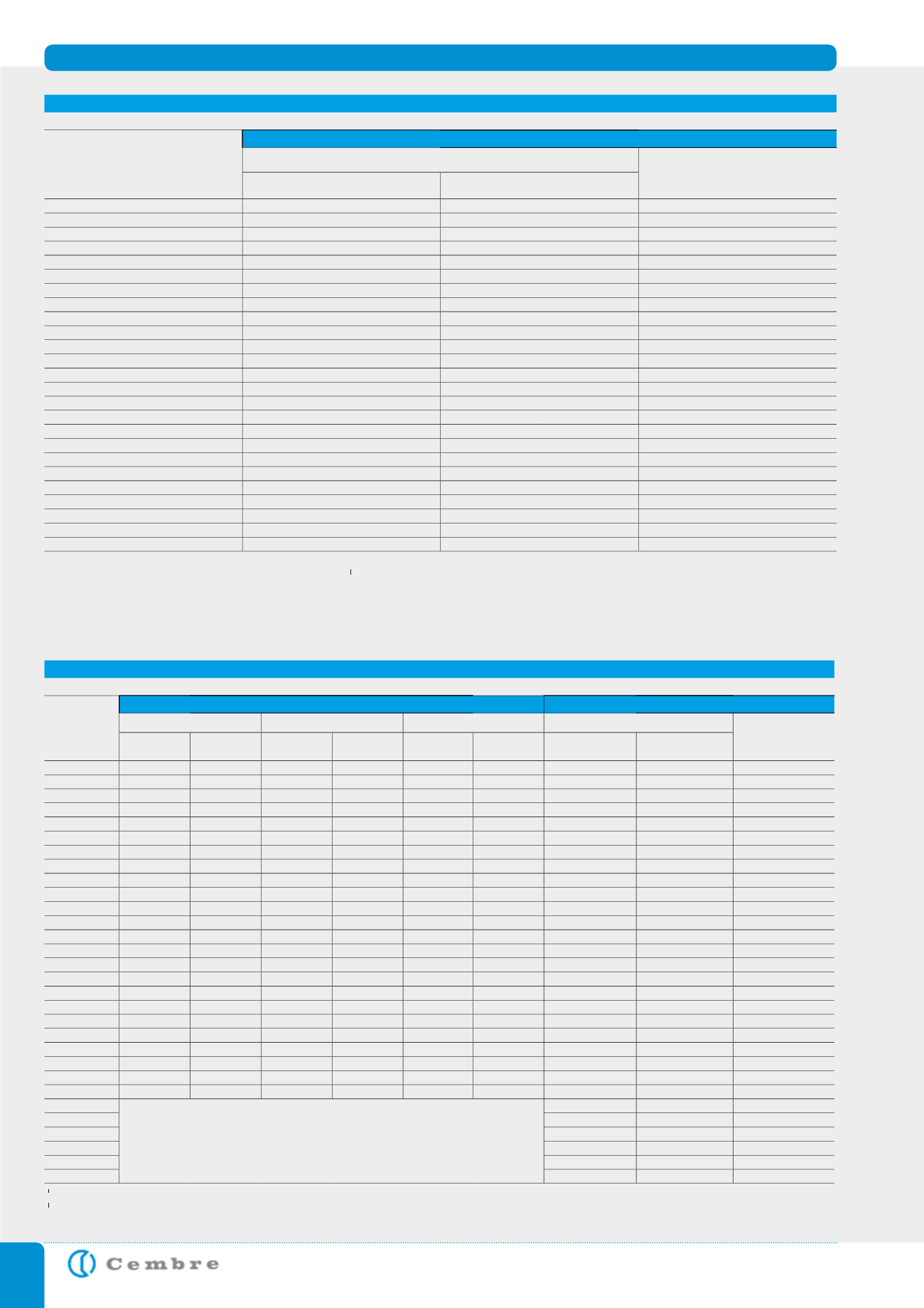
IEC 60228 : 2004 - 11 CONDUCTOR TABLES
CLASS 1:
SOLID CONDUCTORS FOR SINGLE-CORE AND MULTI-CORE CABLES
Nominal cross-sectional
[mm
2
]
Maximum resistance of conductor at 20 °C
Circular, annealed Copper conductors
Aluminium and Aluminium alloy conductors,
circular or shaped
c
[ohm/km]
Plain [ohm/km]
Metal [ohm/km]
0,5
36
36,7
-
0,75
24,5
24,8
-
1
18,1
18,2
-
1,5
12,1
12,2
-
2,5
7,41
7,56
-
4
4,61
4,70
-
6
3,08
3,11
-
10
1,83
1,84
3,08
a
16
1,15
1,16
1,91
a
25
0,727
b
-
1,20
a
35
0,524
b
-
0,868
a
50
0,387
b
-
0,641
70
0,268
b
-
0,443
95
0,193
b
-
0,320
d
120
0,153
b
-
0,253
d
150
0,124
b
-
0,206
d
185
0,101
b
-
0,164
d
240
0,0775
b
-
0,125
d
300
0,0620
b
-
0,100
d
400
0,0465
b
-
0,0778
500
-
-
0,0605
630
-
-
0,0469
800
-
-
0,0367
1000
-
-
0,0291
1200
-
-
0,0247
a
Aluminium conductors 10 mm
2
to 35 mm
2
circular only
b
Solid Copper conductors having nominal cross-sectional area of 25 mm
2
and above are for particular types of cable, e.g. mineral insulated, and not for general purposes.
c
For solid Aluminium alloy conductors, having the same nominal cross-sectional area as an Aluminium conductor, the resistance value given in the table should be multiplied by a factor of
1,162 unless otherwise agreed between the manufacturer and the purchaser.
d
For single core cables, four sectoral shaped conductors may be assembled into a single circular conductor. The maximum resistance of the assembled conductor shall be 25% of that of the
individual component conductors.
CLASS 2:
STRANDED CONDUCTORS FOR SINGLE-CORE AND MULTI-CORE CABLES
Nominal cross-
sectional area
[mm
2
]
Minimum number of wires in the conductor
Maximum resistance of conductor at 20 °C
Circular
Circular compacted
Shaped
Annealed Copper conductor
Aluminium or Aluminium
alloy conductor
c
[ohm/
km]
Cu
Al
Cu
Al
Cu
Al
Plain wires [ohm/km] Metal-coated wires
[ohm/km]
0,5
7
-
-
-
-
-
36,0
36,7
-
0,75
7
-
-
-
-
-
24,5
24,8
-
1,0
7
-
-
-
-
-
18,1
18,2
-
1,5
7
-
6
-
-
-
12,1
12,2
-
2,5
7
-
6
-
-
-
7,41
7,56
-
4
7
-
6
-
-
-
4,61
4,70
-
6
7
-
6
-
-
-
3,08
3,11
-
10
7
7
6
6
-
-
1,83
1,84
3,08
16
7
7
6
6
-
-
1,15
1,16
1,91
25
7
7
6
6
6
6
0,727
0,734
1,20
35
7
7
6
6
6
6
0,524
0,529
0,868
50
19
19
6
6
6
6
0,387
0,391
0,641
70
19
19
12
12
12
12
0,268
0,270
0,443
95
19
19
15
15
15
15
0,193
0,195
0,320
120
37
37
18
15
18
15
0,153
0,154
0,253
150
37
37
18
15
18
15
0,124
0,126
0,206
185
37
37
30
30
30
30
0,0991
0,100
0,164
240
61
61
34
30
34
30
0,0754
0,0762
0,125
300
61
61
34
30
34
30
0,0601
0,0607
0,100
400
61
61
53
53
53
53
0,0470
0,0475
0,0778
500
61
61
53
53
53
53
0,0366
0,0369
0,0605
630
91
91
53
53
53
53
0,0283
0,0286
0,0469
800
91
91
53
53
-
-
0,0221
0,0224
0,0367
1000
91
91
53
53
-
-
0,0176
0,0177
0,0291
1200
b
b
b
b
b
b
0,0151
0,0151
0,0247
1400
a
0,0129
0,0129
0,0212
1600
0,0113
0,0113
0,0186
1800
a
0,0101
0,0101
0,0165
2000
0,0090
0,0090
0,0149
2500
0,0072
0,0072
0,0127
a
Non-preferred sizes. Other non-preferred sizes are recognized for some specialized applications but are not within the scope of this standard.
b
The minimum number of wires for these sizes is not specified. These sizes may be constructed from 4, 5 or 6 equal segments (Milliken).
c
For stranded Aluminium alloy conductors having the same nominal cross-sectional area as an Aluminium conductor the resistance value should be agreed between the manufacturer and the purchaser.