
Total Solution to Earthing & Lightning Protection |
9AKK106354A3360
14/3
14
SPDs should be installed on the line side, as close as
possible to the equipment being protected. Where connected
downstream equipment is > 10 m away, a second SPD
should be installed at the subsequent equipment (in line with
guidance in DD CLC/TS 50539-22:2010).
If the main HV transformer is housed separately from the wind
turbine, incoming/outgoing lines from the turbine and the
HV transformer should be protected (minimum LPZ 0
to LPZ 1, or where control system electronics are installed
LPZ 0 to LPZ 2).
Data/signal/telecoms line protection
SPDs should be installed to protect data, signal and telecoms
lines in the wind turbine and where appropriate, the HV
transformer. A wide range of Furse SPDs are available for this
purpose, including the the ESP SL Series and ESP D, E, H
Series protectors (see Table 3 for specific application).
The SPD selected should be compatible with the system to
be protected, and offer sufficient protection to reduce
overvoltages below the immunity threshold of the protected
equipment. The SPD must not impede system performance
and must be able to survive repeated transients.
Table 3:
SPD requirement according to component to be protected
Location
LPZ
SPD required
Generator (690 V)
LPZ 0 to LPZ 1
ESP WT Series protector
Frequency converter (690 V)
LPZ 0 to LPZ 2 ESP WT Series protector
Transformer (690 V)
LPZ 0 to LPZ 1* ESP WT Series protector
Control system (230 V)
LPZ 0 to LPZ 1 ESP 240 D1 or ESP 240 M1
Aviation warning light (230 V)
LPZ 0 to LPZ 1
ESP 240 D1 or ESP 240 M1
Hub control: – (230 V)
LPZ 0 to LPZ 1
ESP 240 D1 or ESP 240 M1
– (4-20 mA loop)
LPZ 0 to LPZ 1 ESP SL RS485
– (RS 485 line)
LPZ 0 to LPZ 1
ESP SL RS485
Anemometer (24 V)
LPZ 0 to LPZ 1
ESP SL30
Modem
LPZ 0 to LPZ 1 ESP TN or ESP SL TN
*Where the transformer includes process control/data lines, protect to LPZ 2
The SPD should be installed as close as possible to the
point of entry/exit of the incoming/outgoing line. Where
connected equipment is > 10 m from the incoming/outgoing
line, a second SPD should be installed at any subsequent
connected equipment.
SPD
SPD
SPD
SPD
SPD
SPD SPD
SPD
SPD
SPD
LPZ2
LPZ1
LPZ0
LPZ1
LPZ2
LPZ1
LPZ0
Gearbox
Power line690V
Power line230V
Data line
Hubcontrols
Transformer
>10m
Frequency
converter
Modem
Auxilliary
transformer
690V to
230V
Wind
turbine
control
system
Control
cabinet
Anemometer
Aviation
warning
lights
Generator
SPD
SPD
SPD
Power lineSPD230V
Power lineSPD690V
Data lineSPD
SPD
SPD
SPD
SPD
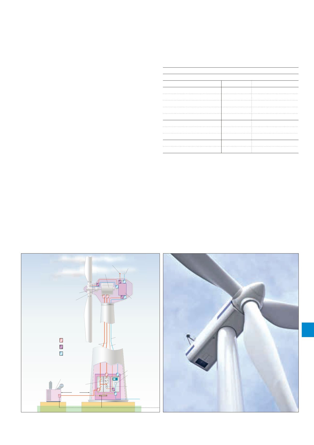
Application of SPDs within a typical wind turbine environment
SPD
SPD
SPD
SPD
SPD
SPD SPD
SPD
SPD
SPD
LPZ2
LPZ1
LPZ0
LPZ1
LPZ2
LPZ1
LPZ0
Gearbox
Power line690V
Power line230V
Data line
Hubcontrols
Transformer
>10m
Frequency
converter
Modem
Auxilliary
transformer
690V to
230V
Wind
turbine
control
system
Control
cabinet
Anemometer
Aviation
warning
lights
Generator
SPD
SPD
SPD
Power lineSPD230V
Power lineSPD690V
Data lineSPD
SPD
SPD
SPD
SPD
SPD
SPD
SPD
SPD
SPD
SPD SPD
SPD
SPD
SPD
LPZ2
LPZ1
LPZ0
LPZ1
LPZ2
LPZ1
LPZ0
Gearbox
Power line690V
Power line230V
Data line
Hubcontrols
Transformer
>10m
Frequency
converter
Modem
Auxilliary
transformer
690V to
230V
Wind
turbine
control
system
Control
cabinet
Anemometer
Aviation
warning
lights
Generator
SPD
SPD
SPD
Power lineSPD230V
Power lineSPD690V
Data lineSPD
SPD
SPD
SPD
SPD
Key
Power line:
–– SPD 690V:
–– SPD 230V:
Data line SPD:
SPD
SPD
SPD
SPD
SPD
SPD SPD
SPD
SPD
SPD
LPZ 2
LPZ 1
LPZ 0
LPZ 1
LPZ 2
LPZ 1
LPZ 0
Gearbox
Power line 690 V
Power line 230 V
Data line
Hub controls
Transformer
>10 m
Frequency
converter
Modem
Auxilliary
transformer
690 V to
230 V
Wind
turbine
control
system
Control
cabinet
Anemometer
Aviation
warning
lights
Generator
SPD
SPD
SPD
Power line SPD 230 V
Power line SPD 690 V
Data line SPD
SPD
SPD
SPD
SPD
SPD
SPD
SPD
SPD
SPD
SPD SPD
SPD
SPD
SPD
LPZ 2
LPZ 1
LPZ 0
LPZ 1
LPZ 2
LPZ 1
LPZ 0
Gearbox
Power line 690 V
Power line 230 V
Data line
Hub controls
Transformer
>10 m
Frequency
converter
Modem
Auxillia y
transformer
690 V to
230 V
Wind
turbine
control
system
Control
cabinet
Anemometer
Aviation
warning
lights
Generator
SPD
SPD
SPD
Power line SPD 230 V
Power line SPD 690 V
Data line SPD
SPD
SPD
SPD
SPD


