


 25 / 300

Furse, Wilford Road, Nottingham, NG2 1EB • Tel: +44 (0)115 964 3700 • Email:
enquiry@furse.com• Web:
www.furse.comProduct selector
Lightning protection
Earth termination network
The means of dissipating the current to the general
mass of earth.
Earth electrodes
Choose an earth electrode to suit
the system design i.e. Type A, Type
B or foundation electrode.
Electrodes can be constructed
individually from earth rods, earth
plates, flat tape, stranded cable or
any combination of these.
Earth rod clamps
Select a high copper content alloy
earth rod clamp for the connection
of the earthing conductor to the
earth rod. In this below ground
application, the clamp must ensure
a good electrical contact and resist
corrosion throughout the lifetime
of the installation.
Earth inspection pits
Select an earth inspection pit to
protect the earth electrode
connections. High strength pits are
available in plastic and concrete.
Equipotential bonding
Bonding is the most commonly employed method of
avoiding the damaging effects of side flashing. All
continuous metalwork should be considered for
bonding. All metallic services, e.g. cable armouring,
gas, water or steam piping, entering the building
should also be bonded as directly as possible to the
earth termination network.
Bonds to metalwork
Select the correct type of
metalwork bond for the
application, i.e. a flat column
face, a circular rainwater pipe or
a ribbed reinforcing bar.
Equipotential bonding SPDs
Designed to prevent dangerous
sparking caused by flashover,
lightning current or equipotential
bonding SPDs
must
be fitted to
all metallic service lines with ‘live
cores’ entering or leaving the
structure.
Product selector
(1) Conductors
p26-39
(2) Conductor fixings
p50-74
(3) Air terminals
p40-49
(4) Air rod bases
p42-44, 49
(5) Conductor jointing clamps
p64-67
(6) Test clamps
p67-69
(7) Crossover conductor clamp
p64
(8) Earth electrodes
p81-84, 88
(9) Earth rod clamps
p92-94
(10) Earth inspection pits
p87
(11) Bonds
p92-106
(12) Lightning current or
Equipotential bonding SPDs
p182-195
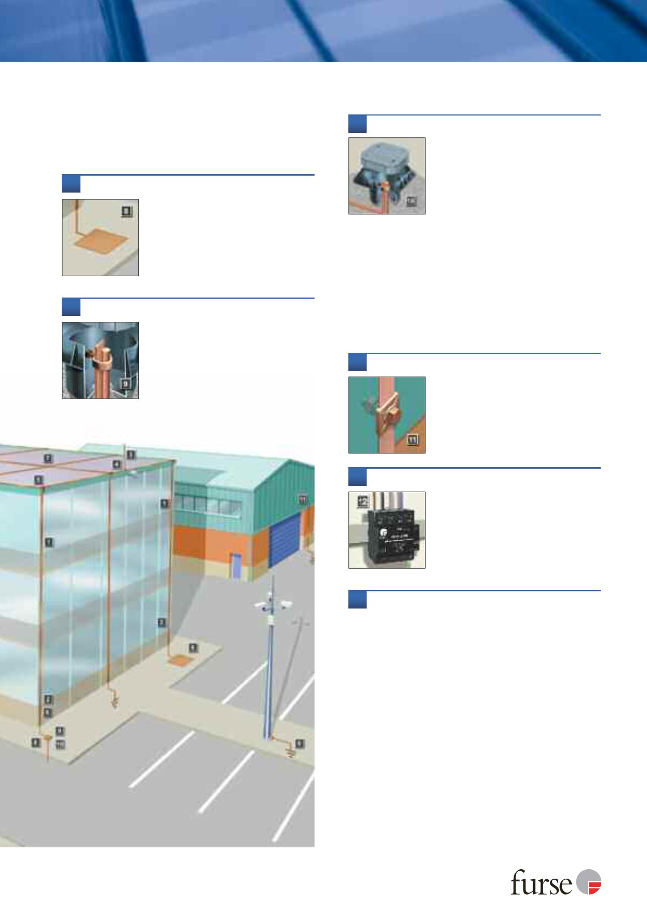
This illustration is designed to demonstrate the main aspects and
individual components of an external lightning protection system.
It is not intended to represent an actual scheme conforming to a
particular code of practice. The drawing is not to scale.