


 24 / 300

Furse, Wilford Road, Nottingham, NG2 1EB • Tel: +44 (0)115 964 3700 • Email:
enquiry@furse.com• Web:
www.furse.comLightning protection
Product selector
Conductors
The first choice faced by the designer of a structural
lightning protection system is the type of conductor
system to be used.
Choose the material required, i.e. copper or aluminium.
Choose the type of conductor required, i.e. flat tape,
solid circular or stranded.
Conductor network
The conductor network is the
means of intercepting/carrying
the current of a lightning strike
safely to the earth termination
network. Use the guidelines of
BS EN 62305-1 & 3 for the correct
placement of conductors.
Fixings
Select the correct system of fixings
for each part of the conductor
system. Fixings are available for a
wide range of modern construction
materials, e.g. brick, stone, plastic
and metal.
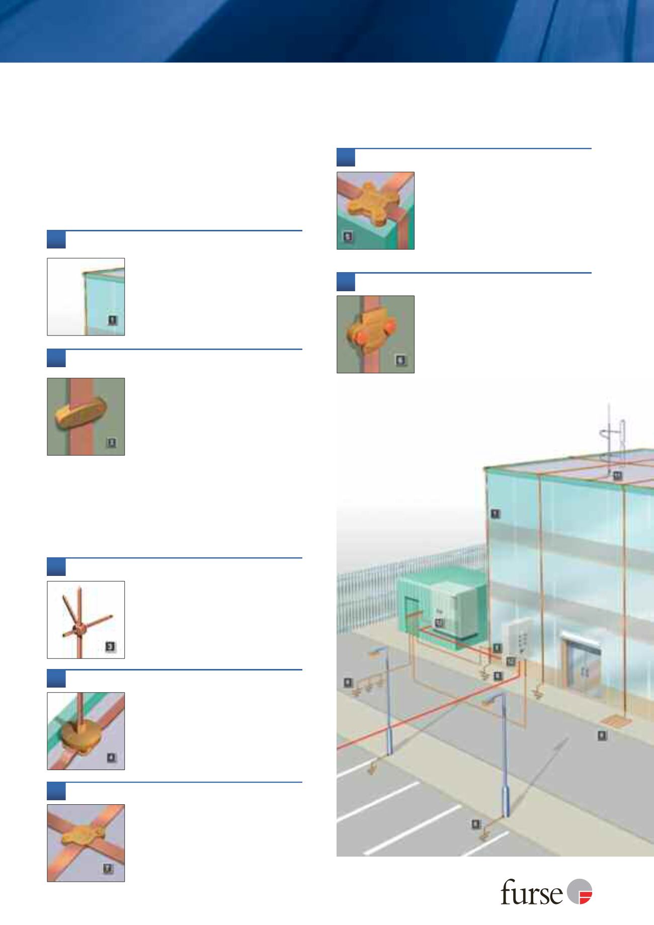
Air termination network
The air termination network is the point of connection
for a lightning strike. It typically consists of a meshed
conductor arrangement covering the roof of the
structure. The mesh size is now determined by
Lightning Protection Level - LPL (see Table 7, page 274).
Air terminals
Use air terminals in the form of
vertical air rods for the protection
of prominent roof top features or
equipment. Use strike pads to
connect and thus expose concealed
conductors.
Air rod bases
Choose the correct air rod base.
This will ensure that the vertical air
rods are both solidly fixed to the
fabric of the structure and have a
low resistance connection to the
conductor network.
Interconnection components
Crossover clamps have been specially
designed for use where conductors
cross as part of a roof network.
Down conductor network
Conductor jointing clamps
Select a component for the
interconnection of multiple
conductors or for changes of
direction. Jointing clamps will
ensure a low resistance, corrosion
resistant connection between air
termination and down conductors.
Test clamps
In order to allow periodic
disconnection and testing of the
earth termination network, select a
test clamp to be placed within the
run of each down conductor.