


 205 / 300

Furse, Wilford Road, Nottingham, NG2 1EB • Tel: +44 (0)115 964 3700 • Email:
enquiry@furse.com• Web:
www.furse.comESP D & TN Series
TSC-0912 - 09.10.12
Technical specification
Derivatives of these protectors are available ready-boxed to IP66, for use in damp or dirty environments. Slim Line (ESP SL), ATEX (ESP SLX)
and PCB mount (ESP PCB) versions are also available. If your system requires a protector with a very low resistance or higher current, see the
ESP E & H Series. Also use the ESP E Series for systems needing a higher bandwidth. Protectors for 3-wire (ESP SL/3W) and RTD (ESP RTD,
ESP SL RTD) are available, as are the space saving protectors (ESP Q, ESP SL Series). The ESP KT and TN Series are additional protectors
specifically for telephone lines. The ESP KS Series are protectors for data and signal lines on an LSA-PLUS module.
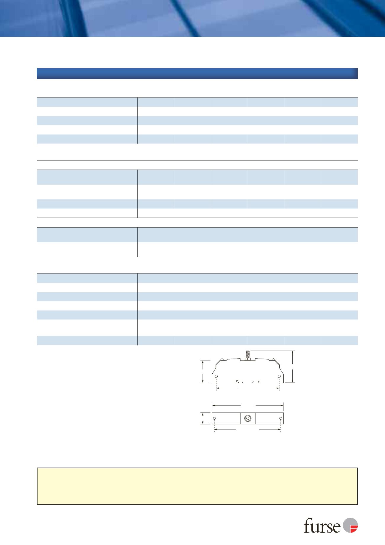
120 mm
38 mm
19 mm
54 mm
105 mm
M4 clearance
109 mm
M4 clearance
1
Nominal voltage (DC or AC peak) measured at < 5 µA
(ESP 15D, ESP 30D, ESP 50D, ESP 110D) and <200 µA
(ESP 06D).
2
Maximum working voltage (DC or AC peak) measured at
< 1 mA leakage (ESP 15D, ESP 30D, ESP 50D, ESP 110D),
< 10 mA (ESP 06D) and < 10 µA (ESP TN).
3
The maximum transient voltage let-through of the protector
throughout the test (±10%), line to line & line to earth, both
polarities. Response time < 10 ns.
4
Test to IEC 61000-4-5:2006, ITU-T (formerly CCITT) K.20,
K.21 and K.45,Telcordia GR-1089-CORE, Issue 2:2002,
ANSI TIA/EIA/IS-968-A:2002 (formerly FCC Part 68).
Electrical specification
ESP 06D
ESP 15D
ESP 30D
ESP 50D
ESP 110D
ESP TN
Nominal voltage
1
6 V
15 V
30 V
50 V
110 V
-
Maximum working voltage
U
c
2
7.79 V
19 V
37.1 V
58 V
132 V
296 V
Current rating
(signal)
300 mA
In-line resistance
(per line ±10%)
9.4
Ω
9.4
Ω
9.4
Ω
9.4
Ω
9.4
Ω
4.4
Ω
Bandwidth
(-3 dB 50
Ω
system)
800 kHz
2.5 MHz
4 MHz
6 MHz
9 MHz
20 MHz
Transient specification
ESP 06D
ESP 15D
ESP 30D
ESP 50D
ESP 110D
ESP TN
Let-through voltage
(all conductors)
3
U
p
C2 test 4 kV 1.2/50 µs, 2 kA 8/20 µs to
BS EN/EN/IEC 61643-21
12.0 V
25.0 V
44.0 V
78.0 V
155 V
395 V
C1 test 1 kV, 1.2/50 µs, 0.5 kA 8/20 µs to
BS EN/EN/IEC 61643-21
11.5 V
24.5 V
43.5 V
76.0 V
150 V
390 V
B2 test 4 kV 10/700 µs to BS EN/EN/IEC 61643-21
10.0 V
23.0 V
42.5 V
73.0 V
145 V
298 V
5 kV, 10/700 µs
4
10.5 V
23.8 V
43.4 V
74.9 V
150 V
300 V
Maximum surge current
D1 test 10/350 µs to
- per signal wire
BS EN/EN/IEC 61643-21
- per pair
2.5 kA
5 kA
8/20 µs to ITU-T K.45:2003, - per signal wire
IEEE C62.41.2:2002
- per pair
10 kA
20 kA
Mechanical specification
ESP 06D
ESP 15D
ESP 30D
ESP 50D
ESP 110D
ESP TN
Temperature range
-40 to +80 ºC
Connection type
Screw terminal
Conductor size
(stranded)
2.5 mm
2
Earth connection
M6 stud
Case material
ABS UL94 V-0
Weight -
unit
0.08 kg
Weight
-
packaged (per 10)
0.85 kg
Dimensions