


 195 / 300

Furse, Wilford Road, Nottingham, NG2 1EB • Tel: +44 (0)115 964 3700 • Email:
enquiry@furse.com• Web:
www.furse.comESP M1R, M2R, M4R Series
TSC-0912 - 09.10.12
Technical specification
Electrical specification
ESP 415 M1R ESP 480 M1R ESP 415 M2R ESP 480 M2R ESP 415 M4R ESP 480 M4R
Nominal voltage - Phase-Neutral
U
o
(RMS)
240 V
277 V
240 V
277 V
240 V
277 V
Maximum voltage - Phase-Neutral
U
c
(RMS)
280 V
350 V
280 V
350 V
280 V
350 V
Temporary Overvoltage TOV
U
T
1
350 V
402 V
350 V
402 V
350 V
402 V
Short circuit withstand capability
25 kA, 50 Hz
Working voltage
(RMS)
346-484 V
402-600 V
346-484 V
402-600 V
346-484 V
402-600 V
Frequency range
47-63 Hz
Max. back-up fuse
(see installation instructions)
125 A
125 A
200 A
200 A
315 A
315 A
Leakage current
(to earth)
< 250 µA
< 250 µA
< 500 µA
<500 µA
< 1000 µA
< 1000 µA
Indicator circuit current
< 10 mA
< 10 mA
< 20 mA
< 20 mA
< 40 mA
< 40 mA
Volt free contact
2
- current rating
- nominal voltage
(RMS)
Screw terminal
1 A
250 V
Transient specification
ESP 415 M1R ESP 480 M1R ESP 415 M2R ESP 480 M2R ESP 415 M4R ESP 480 M4R
Type 1 (BS EN/EN), Class I (IEC)
Nominal discharge current 8/20 µs (per mode)
I
n
20 kA
20 kA
40 kA
40 kA
80 kA
80 kA
Let-through voltage
U
p at
I
n
3
900 V
1 kV
900 V
1 kV
900 V
1 kV
Impulse discharge current 10/350 µs
I
imp
(per mode)
4
4 kA
4 kA
8 kA
8 kA
16 kA
16 kA
Let-through voltage
U
p at
I
imp
3
750 V
850 V
750 V
850 V
750 V
850 V
Impulse discharge current (per phase)
l
imp
5
6.25 kA
6.25 kA
12.5 kA
12.5 kA
25 kA
25 kA
Type 2 (BS EN/EN), Class II (IEC)
Nominal discharge current 8/20 µs (per mode)
I
n
20 kA
20 kA
40 kA
40 kA
80 kA
80 kA
Let-through voltage
U
p at
I
n
3
900 V
1 kV
900 V
1 kV
900 V
1 kV
Maximum discharge current
I
max (per mode)
4
40 kA
40 kA
80 kA
80 kA
160 kA
160 kA
Maximum discharge current
I
max (per phase)
80 kA
80 kA
160 kA
160 kA
320 kA
320 kA
Type 3 (BS EN/EN), Class III (IEC)
Let-through voltage at
U
oc of 6 kV 1.2/50 µs and
I
sc of 3 kA 8/20 µs (per mode)
6
600 V
680 V
590 V
670 V
570 V
650 V
Mechanical specification
ESP 415 M1R ESP 480 M1R ESP 415 M2R ESP 480 M2R ESP 415 M4R ESP 480 M4R
Temperature range
-40 to +80 ºC
Connection type
Screw terminal
Conductor size
(stranded)
16 mm
2
16 mm
2
25 mm
2
25 mm
2
50 mm
2
50 mm
2
Earth connection
Screw terminal
Volt free contact
Connect via screw terminal with conductor up to 2.5 mm
2
(stranded)
Degree of protection
(IEC 60529)
IP20
Display connection
6 way 1 metre interconnection cable - 2 or 4 metre cable optional
Case material
Unit - Steel, Display - ABS
Weight -
unit
1.1 kg
1.1 kg
2.45 kg
2.45 kg
4 kg
4 kg
-
packaged
1.2 kg
1.2 kg
2.55 kg
2.55 kg
4.3 kg
4.3 kg
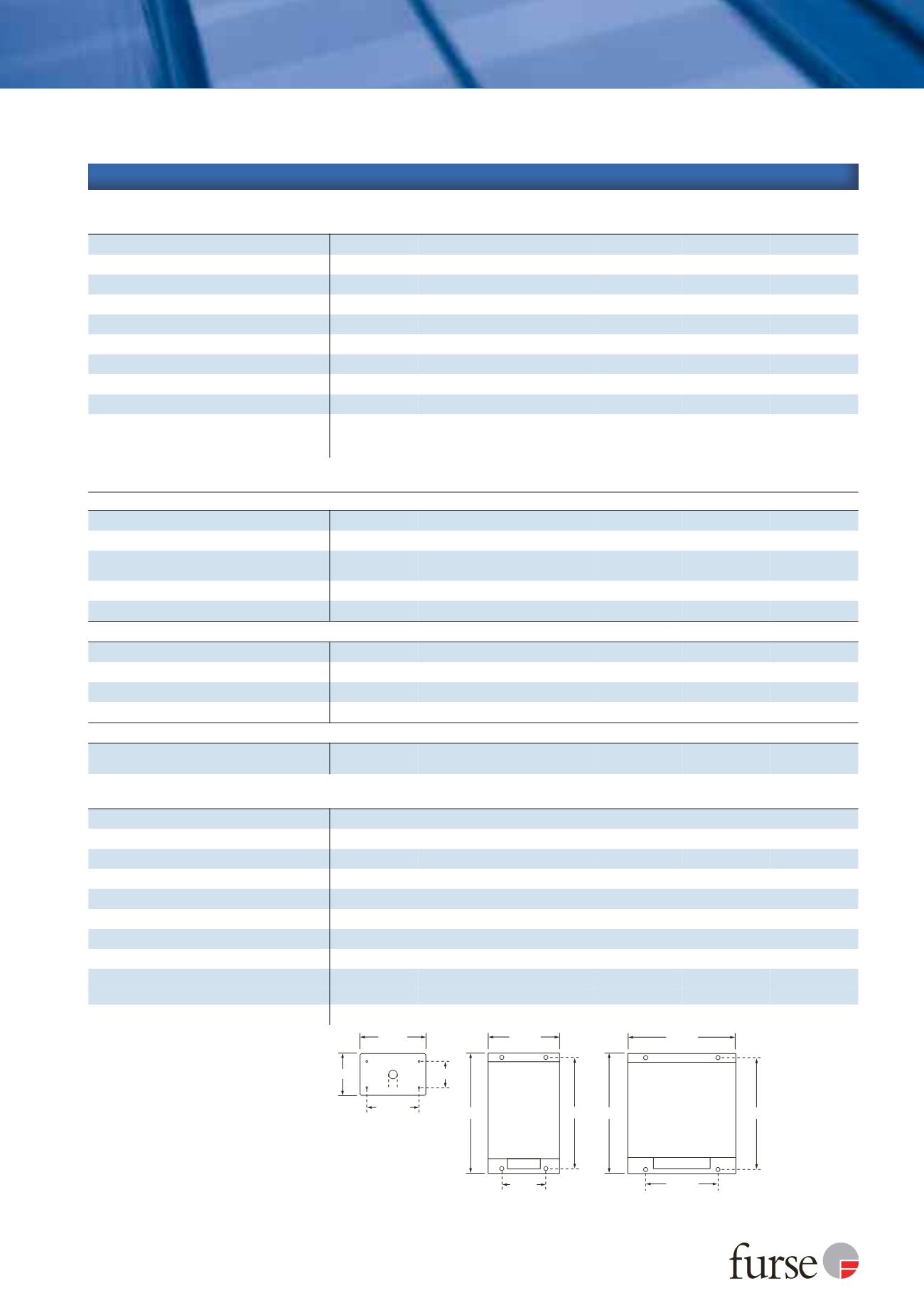
Dimensions
ESP XXX M1R
110 mm
90 mm
165 mm
35.5 mm
70 mm
70.5 mm
Ø 15 mm
ESP XXX M2R/M4R
M5 Clearance
Note: The unit takes
up 20 mm (ESP M1),
or 25 mm (ESP M2/M4)
of the length of the
fixing screw
Display unit (rear view)
M3 threaded
Depth: 12 mm
(60 mm depth required
behind panel for plug)
Depth:
73 mm (ESP M1R)
78 mm (ESP M2R)
125 mm (ESP M4R)
226 mm
176 mm
204 mm
180 mm
55 mm
186.5 mm
1
Temporary Overvoltage rating is for a maximum duration of
5 seconds tested to BS EN/EN/IEC 61643.
2
Minimum permissable load is 5 V DC, 10 mA to ensure
reliable operation. Under fault conditions, the remote display
will go blank if the L1 phase loses power or becomes faulty.
This is due to the isolation requirements needed for circuitry
mounted externally to the main protector unit.
3
The maximum transient voltage let-through of the protector
throughout the test (±5%), phase to neutral, phase to earth
and neutral to earth.
4
The electrical system, external to the unit, may constrain the
actual current rating achieved in a particular installation.
5
Rating is considered as the current capability of the protector
for equipotential bonding near the service entrance.
6
Combination wave test within BS EN/IEC 61643,
IEEE C62.41-2002 Location Cats C1 & B3, SS 555:2010,
AS/NZS 1768-2007, UL 1449 mains wire-in.