


 193 / 300

Furse, Wilford Road, Nottingham, NG2 1EB • Tel: +44 (0)115 964 3700 • Email:
enquiry@furse.com• Web:
www.furse.comESP M1 Series
TSC-0912 - 09.10.12
Technical specification
Single
Phase
Three
Phase
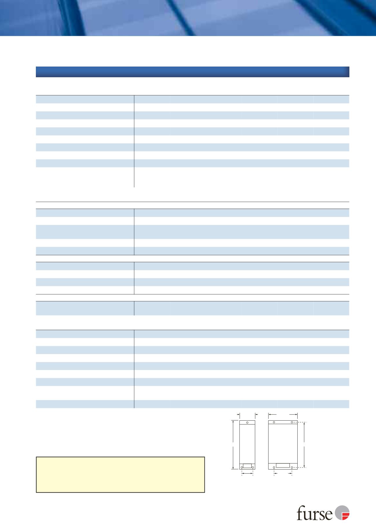
M5 Clearance
Note: The unit
takes up 20 mm
of the length of
the fixing screw
Depth:
73 mm
60 mm
110 mm
45.5 mm
180 mm
165 mm
70 mm
If you desire a protector with an extra high maximum surge current use
the ESP M2 or ESP M4 series. If your supply is fused at 16 amps, or less, the
in-line protectors (ESP 240 or 120-5A (or -16A) and their ready-boxed
derivatives) may be more suitable. If you need to mount the display panel
separately from the main protector unit, use the ESP M1R series.
Electrical specification
ESP 120 M1 ESP 208 M1 ESP 240 M1 ESP 415 M1 ESP 277 M1 ESP 480 M1
Nominal voltage - Phase-Neutral
U
o
(RMS)
120 V
120 V
240 V
240 V
277 V
277 V
Maximum voltage - Phase-Neutral
U
c
(RMS)
150 V
150 V
280 V
280 V
350 V
350 V
Temporary Overvoltage TOV
U
T
1
175 V
175 V
350 V
350 V
402 V
402 V
Short circuit withstand capability
25 kA, 50 Hz
Working voltage
(RMS)
90-150 V
156-260 V
200-280 V
346-484 V
232-350 V
402-600 V
Frequency range
47-63 Hz
Max. back-up fuse
(see installation instructions)
125 A
Leakage current
(to earth)
< 250 µA
Indicator circuit current
< 10 mA
Volt free contact
2
- current rating
- nominal voltage
(RMS)
Screw terminal
1 A
250 V
Transient specification
ESP 120 M1 ESP 208 M1 ESP 240 M1 ESP 415 M1 ESP 277 M1 ESP 480 M1
Type 1 (BS EN/EN), Class I (IEC)
Nominal discharge current 8/20 µs (per mode)
I
n
20 kA
Let-through voltage
U
p at
I
n
3
600 V
600 V
900 V
900 V
1 kV
1 kV
Impulse discharge current 10/350 µs
I
imp
(per mode)
4
4 kA
Let-through voltage
U
p at
I
imp
3
500 V
500 V
750 V
750 V
850 V
850 V
Impulse discharge current (per phase)
l
imp
5
6.25 kA
Type 2 (BS EN/EN), Class II (IEC)
Nominal discharge current 8/20 µs (per mode)
I
n
20 kA
Let-through voltage
U
p at
I
n
3
600 V
600 V
900 V
900 V
1 kV
1 kV
Maximum discharge current
I
max (per mode)
4
40 kA
Maximum discharge current
I
max (per phase)
80 kA
Type 3 (BS EN/EN), Class III (IEC)
Let-through voltage at
U
oc of 6 kV 1.2/50 µs and
I
sc of 3 kA 8/20 µs (per mode)
6
390 V
390 V
600 V
600 V
680 V
680 V
Mechanical specification
ESP 120 M1 ESP 208 M1 ESP 240 M1 ESP 415 M1 ESP 277 M1 ESP 480 M1
Temperature range
-40 to +80 ºC
Connection type
Screw terminal
Conductor size
(stranded)
16 mm
2
Earth connection
Screw terminal
Volt free contact
Connect via screw terminal with conductor up to 2.5 mm
2
(stranded)
Degree of protection
(IEC 60529)
IP20
Case material
Steel
Weight -
unit
0.6 kg
1.0 kg
0.6 kg
1.0 kg
0.6 kg
1.0 kg
Weight
-
packaged
0.7 kg
1.1 kg
0.7 kg
1.1 kg
0.7 kg
1.1 kg
Dimensions
1
Temporary Overvoltage rating is for a maximum duration of 5 seconds tested to BS EN/EN/IEC 61643.
2
Minimum permissable load is 5 V DC, 10 mA to ensure reliable operation.
3
The maximum transient voltage let-through of the protector throughout the test (±5%), phase to neutral, phase
to earth and neutral to earth.
4
The electrical system, external to the unit, may constrain the actual current rating achieved in a particular
installation.
5
Rating is considered as the current capability of the protector for equipotential bonding near the service entrance.
6
Combination wave test within BS EN/IEC 61643, IEEE C62.41-2002 Location Cats C1 & B3, SS 555:2010,
AS/NZS 1768-2007, UL 1449 mains wire-in.