


 191 / 300

Furse, Wilford Road, Nottingham, NG2 1EB • Tel: +44 (0)115 964 3700 • Email:
enquiry@furse.com• Web:
www.furse.comESP M2/M4 Series
TSC-0912 - 09.10.12
Technical specification
Electrical specification
ESP 415 M2
ESP 415 M4
ESP 480 M2
ESP 480 M4
Nominal voltage - Phase-Neutral
U
o
(RMS)
240 V
240 V
277 V
277 V
Maximum voltage - Phase-Neutral
U
c
(RMS)
280 V
280 V
350 V
350 V
Temporary Overvoltage TOV
U
T
1
350 V
350 V
402 V
402 V
Short circuit withstand capability
25 kA, 50 Hz
Working voltage
(RMS)
346-484 V
346-484 V
402-600 V
402-600 V
Frequency range
47-63 Hz
Max. back-up fuse
(see installation instructions)
200 A
315 A
200 A
315 A
Leakage current
(to earth)
< 500 µA
< 1000 µA
< 500 µA
< 1000 µA
Indicator circuit current
< 20 mA
< 40 mA
< 20 mA
< 40 mA
Volt free contact
2
- current rating
- nominal voltage
(RMS)
Screw terminal
1 A
250 V
Transient specification
ESP 415 M2
ESP 415 M4
ESP 480 M2
ESP 480 M4
Type 1 (BS EN/EN), Class I (IEC)
Nominal discharge current 8/20 µs (per mode)
I
n
40 kA
80 kA
40 kA
80 kA
Let-through voltage
U
p at
I
n
3
900 V
900 V
1 kV
1 kV
Impulse discharge current 10/350 µs
I
imp
(per mode)
4
8 kA
16 kA
8 kA
16 kA
Let-through voltage
U
p at
I
imp
3
750 V
750 V
850 V
850 V
Impulse discharge current (per phase)
l
imp
5
12.5 kA
25 kA
12.5 kA
25 kA
Type 2 (BS EN/EN), Class II (IEC)
Nominal discharge current 8/20 µs (per mode)
I
n
40 kA
80 kA
40 kA
80 kA
Let-through voltage
U
p at
I
n
3
900 V
900 V
1 kV
1 kV
Maximum discharge current
I
max (per mode)
4
80 kA
160 kA
80 kA
160 kA
Maximum discharge current
I
max (per phase)
160 kA
320 kA
160 kA
320 kA
Type 3 (BS EN/EN), Class III (IEC)
Let-through voltage at
U
oc of 6 kV 1.2/50 µs and
I
sc of 3 kA 8/20 µs (per mode)
6
590 V
570 V
670 V
650 V
Mechanical specification
ESP 415 M2
ESP 415 M4
ESP 480 M2
ESP 480 M4
Temperature range
-40 to +80 ºC
Connection type
Screw terminal
Conductor size
(stranded)
25 mm
2
50 mm
2
25 mm
2
50 mm
2
Earth connection
Screw terminal
Volt free contact
Connect via screw terminal with conductor up to 2.5 mm
2
(stranded)
Degree of protection
(IEC 60529)
IP20
Case material
Steel
Weight -
unit
2.35 kg
3.9 kg
2.35 kg
3.9 kg
Weight
-
packaged
2.5 kg
4.2 kg
2.5 kg
4.2 kg
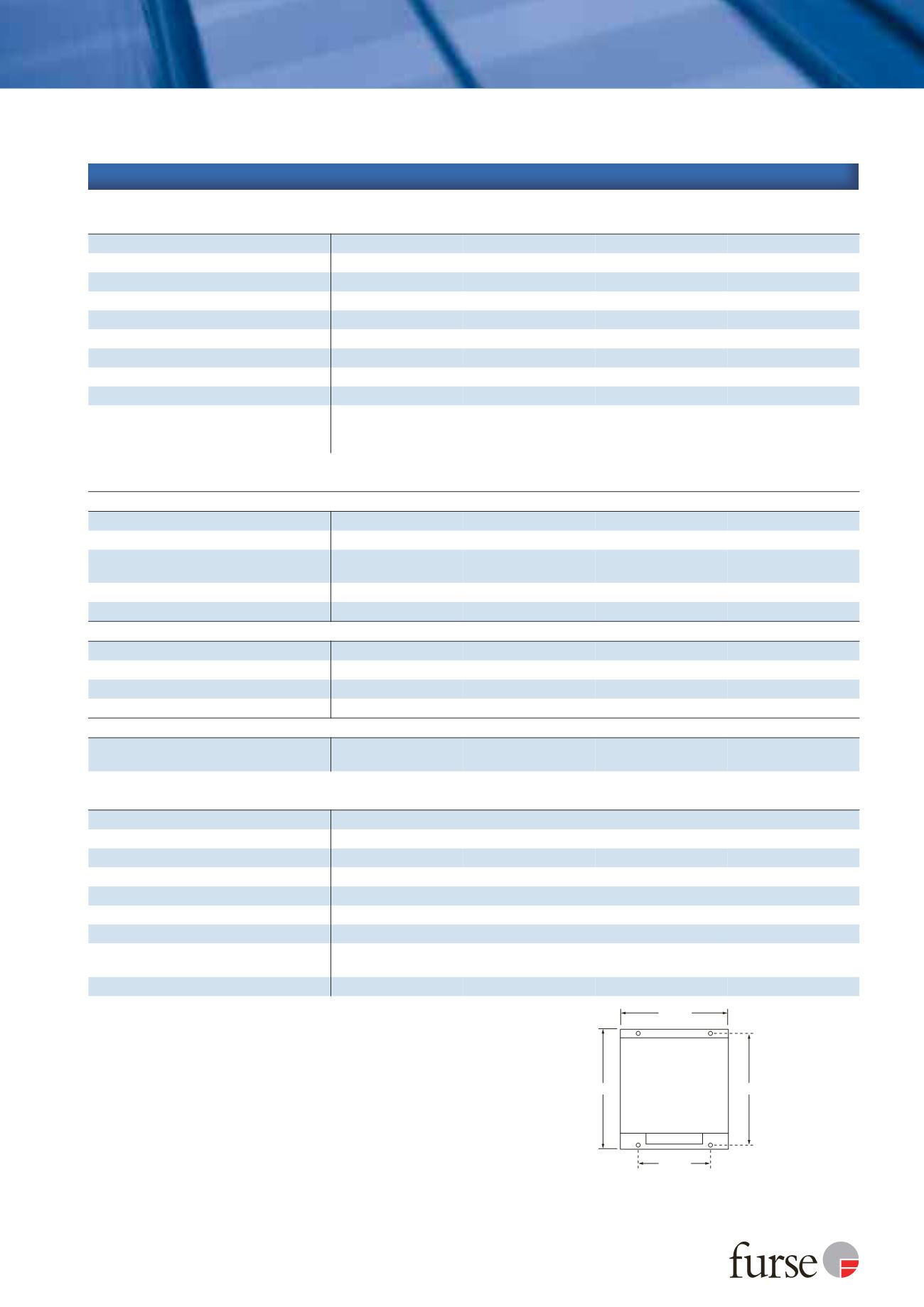
Dimensions
ESP XXX M2/M4
M5 Clearance
Note: The unit
takes up 25 mm
of the length of
the fixing screw
Depth:
78 mm (ESP M2)
125 mm (ESP M4)
226 mm
176 mm
204 mm
186.5 mm
1
Temporary Overvoltage rating is for a maximum duration of 5 seconds tested to BS EN/EN/IEC 61643.
2
Minimum permissable load is 5 V DC, 10 mA to ensure reliable operation.
3
The maximum transient voltage let-through of the protector throughout the test (±5%), phase to neutral, phase to
earth and neutral to earth.
4
The electrical system, external to the unit, may constrain the actual current rating achieved in a particular installation.
5
Rating is considered as the current capability of the protector for equipotential bonding near the service entrance.
6
Combination wave test within BS EN/IEC 61643, IEEE C62.41-2002 Location Cats C1 & B3, SS 555:2010,
AS/NZS 1768-2007, UL 1449 mains wire-in.