


 11 / 73

10
LADDER language
Definition
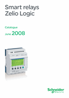
Text function block
Up/down counter
Analogue comparator
Control relay
LCD backlighting
Output coil
Timer
Fast counter
Clock
Counter comparator
Summer/Winter time switching
Message
LADDER language enables a LADDER program to be written with elementary
functions, elementary function blocks and derived function blocks, as well as with
contacts, coils and variables.
The contacts, coils and variables can be annotated. Text can be placed freely within
the graphic.
Control scheme input modes
“Zelio input” mode enables users who have directly programmed the Zelio Logic
smart relay to find the same user interface, even when using the software for the first
time.
“Free input” mode, which is more intuitive, is very user-friendly and incorporates
many additional features.
With LADDER programming language, two alternative types of symbol can be used:
LADDER symbols,
electrical symbols.
“Free input” mode also allows the creation of mnemonics and notes associated with
each line of the program.
Instant switching from one input mode to the other is possible at any time, by simply
clicking the mouse.
Up to 120 control scheme lines can be programmed, with 5 contacts and 1 coil per
program line
Functions:
16 Text function blocks,
16 time delay function blocks; parameters of 11 different types can be set for each
of these (1/10
th
second to 9999 hours),
16 up/down counter function blocks from 0 to 32767,
1 fast counter (1 kHz),
16 analogue comparator function blocks,
8 clock function blocks, each with 4 channels,
28 control relays,
8 counter comparators,
LCD screen with programmable backlighting,
automatic Summer/Winter time switching,
variety of functions: coil, latching (Set/Reset), impulse relay, contactor,
28 message blocks (with communication interface, see page 48).
b
v
v
b
v
v
v
v
v
v
v
v
v
v
v
v
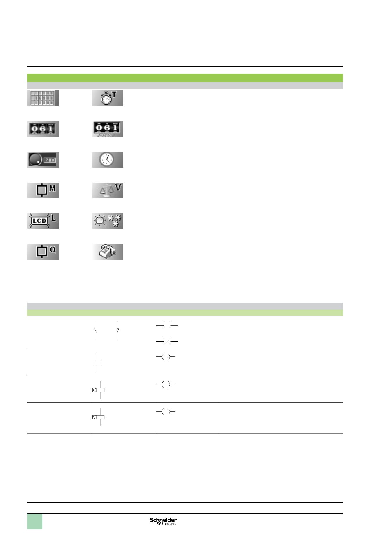
Functions
Function
Electrical scheme
LADDER language
Notes
Contact
I corresponds to the real state of the contact connected to the
input of the smart relay.
i corresponds to the inverse state of the contact connected to
the input of the smart relay.
Standard coil
The coil is energised when the contacts to which it is connected
are closed.
Latch coil (Set)
The coil is energised (set) when the contacts to which it is
connected are closed. It remains set even if the contacts are no
longer closed.
Unlatch coil (Reset)
The coil is de-energised (reset) when the contacts to which it is
connected are closed.
It remains disabled even if the contacts are no longer closed.
13
14
22 21
or
or
I
i
A1
A2
A1
A2
S
A1
A2
R
Presentation :
pages 6 to 9
Characteristics :
pages 14 to 19
Curves :
pages 20 and 21
References :
pages 22 to 27
Dimensions, schemes :
pages 28 to 31
Functions
1
Zelio Logic smart relays
1
Compact and modular smart relays
“Zelio Soft 2” programming software
1
2
3
4
5
6
7
8
9
10