


 14 / 413

1/8
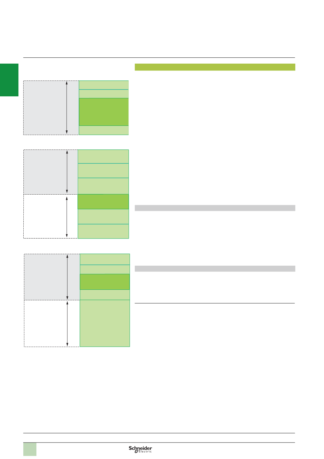
Memory structure
The application memory is divided into memory areas, which are physically
distributed across the internal RAM and 0, 1 or 2 PCMCIAmemory extension cards:
1
The application data area, which is always found in the internal RAM, is divided
into two possible types:
v
Located data, corresponding to data defined by an address (e.g. %MW237),
which can have a symbol linked to it (e.g. Counter_rejects).
v
Unlocated data, corresponding to data defined only by a symbol. This type of
addressing eliminates the problems of memory mapping management, because
addresses are assigned automatically.
v
DFB unlocated data corresponding to DFB user function block data. The size of
this area (which is determined by the physical size of the available internal RAM)
depends on the processor model, see pages 1/10 and 1/11.
2
Area in internal RAM or PCMCIAmemory card for the program and symbols.
If this area is inside the internal RAM, it also supports the area for program
modification in online mode
(1)
.
This area contains the program's executable binary code and IEC source code.
The user selects the type of information to be stored in the PLC memory.
3
Constants area in the internal RAM or the PCMCIAmemory card (slot no. 0)
4
Area for storing additional data (slot no. 0 or no. 1), e.g. for production data and
manufacturing recipes
Memory organization
The memory will be organized in one of two ways, depending on whether the
Premium processor is fitted with 0, 1 or 2 memory extension cards:
b
Application in internal RAM: The application is completely loaded into the
processor's internal battery-backed RAM
(2)
,
the capacity of which depends on the
processor model (96 Kb to 2 Mb).
b
Application in PCMCIA card: In this case, the internal RAM is reserved for
application data. The PCMCIAmemory card (slot no. 0) contains the program space
(
program, symbols and constants areas) (128 Kb to 2 Mb). Certain types of PCMCIA
memory card also host the data storage area (max. 6976 Kb).
Symbols areas
Having the symbols area in the same place as the program area is optional.
However, if the application symbols database is available on the PLC, it means that,
when an empty programming terminal is connected to the PLC, all the elements
needed to debug or upgrade this PLC can be transferred to the terminal.
(1)
If a PCMCIA card has been inserted, it is the memory on this memory card that will be used
for modification of the program in online mode (outside areas 2, 3 and 4 opposite).
(2)
The internal RAM is backed up by an optional battery (with a life of 3 years), which is located
in the power supply module (see page 2/2).
Memory structure
Presentation:
page 1/4
Description:
pages 1/5 …
References:
pages 1/10 …
PCMCIA references:
pages 1/12 …
Modicon Premium automation
platform
0
Unity processors
1
1
2
3
4
Internal RAM
Data storage
PCMCIA card
(
slot no. 0)
Located data
96
to 2048 Kb
4096
or 8192 KB
Processor with data storage memory card in slot no. 0
Program, symbols and
area for program
modification in onlinemode
Constants
Additional data storage
Unlocated data
1
2
3
4
1
1
Internal RAM
PCMCIA card
(
slot no. 0)
Located data
96
to 2048 Kb
Processor with PCMCIAmemory card in slot no. 0
128
to 7168 Kb
Global unlocated data
Program and symbols
Constants
Additional data storage
1
1
2
3
Internal RAM
96
to 2048 Kb
Processor without PCMCIAmemory card
Located data
Global unlocated
data and DFBs
Program, symbols and
area for program
modification in online
mode
Constants
DFB unlocated data
2
1
3
4
5
6
7
8
9
10