


 353 / 356

D-105
Connection of power cables
Additional informations
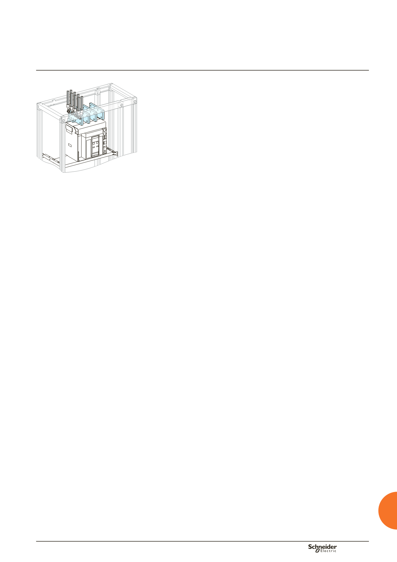
DD380794
Connecting to terminal extension bars
Check that the circuit and switchgear identification indications match.
When connections are made to terminal extensions made up of several bars for
each phase, position the lugs opposite one another and insert copper spacers
between the bars.
Comply with the minimum required electrical clearances between phases of
14 mm (conforming with IEC 60439-1).
Mark all nuts and the terminal extension bars with a dot of varnish after tightening
to the defined torque.
Remove the top cross-member of the cubicle to simplify connection of the cables
to the bars.
Tie cables of the same phase together.
Connection directly to device terminals
When connections are made directly to the switchgear terminals, comply with the
tightening torque recommended by the device manufacturer.
Check that the length of the screws delivered with the switchgear is compatible
with the lug thickness.
Comply with the safety clearances around the switchgear devices, defined by the
manufacturer to ensure correct operation.
Refit the interphase barriers and terminal shields if applicable after connection the
power cables.
For the special case of connection with armoured cable, please consult us.
b
b
b
b
b
b
b
b
b
b
b
Removable upper cross-member.
Practical information