


 350 / 356

D-102
Connection of busbar trunking
Additional informations
Prisma Plus switchboards come equipped with a special interface that allows them
to be directly connected to Canalis KT trunking.
The electrical connection between the Canalis KT trunking and the Prisma Plus
switchboard is just as easy to carry out as jointing between two busbar trunking
sections.
The Canalis KT interface is totally integrated in the Prisma Plus switchboard volume.
It comprises a Canalis KT joint block and interface/circuit breaker connection
terminals.
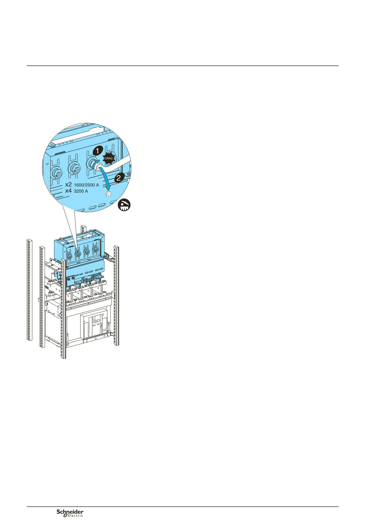
Trunking connection via the top
Dismantle the roof.
Cut out a passage for the busbar trunking.
Adjust the guides according to the KT width that will be connected.
Unscrew the junction block screws.
Ensure that the busbar trunking length to be connected to the switchboard is
correctly supported and that it is not resting on the interface.
Lower the element until it is in contact with the interface frame, without bearing on
it.
Tighten the junction torque nuts. When the head breaks, the torque of 60 Nm has
been reached.
d
In certain cases, it is recommended to only tighten the 2 middle nuts to 60 Nm
and the 2 outer nuts to 10 Nm.
A red plastic washer that is ejected when the head breaks provides visual
evidence that the joint tightening operation has been carried out correctly.
For dismantling or maintenance operations, a second head is available on the nut
and can be retightened using a conventional torque wrench. The recommended
tightening torque is then 60 Nm.
Reassemble the roof.
Sealing kit
In order to retain the original IP index, use the roof sealing kit ordered with the
busbar trunking. This kit guarantees an IP52 degree of protection at the trunking
passage.
The kit is installed by cutting out the roof of the Prisma Plus switchboard. This cut-
out, which is the same dimension for all Canalis KT busbar trunking ratings, is made
using the template delivered with the sealing kit.
b
b
b
b
b
b
b
b
b
b
b
b
DD383919
Practical information