


 278 / 356

D-30
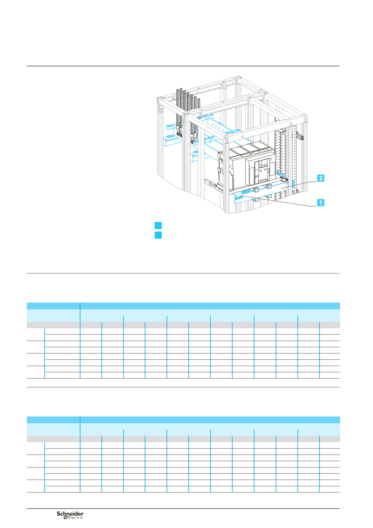
Masterpact NW08 to NW32
Fixed, top or bottom connection
DD383667
1
Connection.
2
Horizontal link.
Using the data below, it is possible to determine the size of the copper bars and the
maximum permissible currents when making the connections to busbars for a
vertical, fixed Masterpact NW08/NW32, front or rear connection, taking into account
the ambient temperature around the switchboard and the IP value.
Connection
Flat bars, 5 mm thick
Device
Permissible current (A)
Ambient temperature around the switchboard
25 °C
30 °C
35 °C
40 °C
45 °C
50 °C
IP
y
31 IP > 31 IP
y
31 IP > 31 IP
y
31 IP > 31 IP
y
31 IP > 31 IP
y
31 IP > 31 IP
y
31 IP > 31
NW08 Size per phase 1b 80 x 5 1b 80 x 5 1b 80 x 5 1b 80 x 5 1b 80 x 5 1b 80 x 5 1b 80 x 5 1b 80 x 5 1b 80 x 5 1b 80 x 5 1b 80 x 5
b
I (A)
800
800
800
800
800
800
800
800
800
800
800
NW10 Size per phase 1b 80 x 5 1b 80 x 5 1b 80 x 5 1b 80 x 5 1b 80 x 5 1b 80 x 5 1b 80 x 5 1b 80 x 5 1b 80 x 5 1b 80 x 5 1b 80 x 5
b
I (A)
1000 1000 1000 1000 1000 1000 1000 1000 1000 1000 1000
NW12 Size per phase 2b 80 x 5 2b 80 x 5 2b 80 x 5 2b 80 x 5 2b 80 x 5 2b 80 x 5 2b 80 x 5 2b 80 x 5 2b 80 x 5 2b 80 x 5 2b 80 x 5
b
I (A)
1250 1250 1250 1250 1250 1250 1250 1250 1250 1250 1250
NW16 Size per phase 2b 80 x 5 2b 80 x 5 2b 80 x 5 2b 80 x 5 2b 80 x 5 2b 80 x 5 2b 80 x 5 2b 80 x 5 2b 80 x 5 2b 80 x 5 2b 80 x 5
b
I (A)
1600 1600 1600 1570 1600 1520 1570 1470 1520 1420 1470
Horizontal link
Flat bars, 5 mm thick
Device
Permissible current (A)
Ambient temperature around the switchboard
25 °C
30 °C
35 °C
40 °C
45 °C
50 °C
IP
y
31 IP > 31 IP
y
31 IP > 31 IP
y
31 IP > 31 IP
y
31 IP > 31 IP
y
31 IP > 31 IP
y
31 IP > 31
NW08 Size per phase 1b 80 x 5 1b 80 x 5 1b 80 x 5 1b 80 x 5 1b 80 x 5 1b 80 x 5 1b 80 x 5 1b 80 x 5 1b 80 x 5 1b 80 x 5 1b 80 x 5
b
I (A)
800
800
800
800
800
800
800
800
800
800
800
NW10 Size per phase 1b 80 x 5 1b 80 x 5 1b 80 x 5 1b 80 x 5 1b 80 x 5 1b 80 x 5 1b 80 x 5 1b 80 x 5 1b 80 x 5 1b 80 x 5 1b 80 x 5
b
I (A)
1000 1000 1000 1000 1000 1000 1000 1000 1000 1000 1000
NW12 Size per phase 2b 80 x 5 2b 80 x 5 2b 80 x 5 2b 80 x 5 2b 80 x 5 2b 80 x 5 2b 80 x 5 2b 80 x 5 2b 80 x 5 2b 80 x 5 2b 80 x 5
b
I (A)
1250 1250 1250 1250 1250 1250 1250 1250 1250 1250 1250
NW16 Size per phase 2b 80 x 5 2b 80 x 5 2b 80 x 5 2b 80 x 5 2b 80 x 5 2b 80 x 5 2b 80 x 5 2b 80 x 5 2b 80 x 5 2b 80 x 5 2b 80 x 5
b
I (A)
1600 1600 1600 1570 1600 1520 1570 1470 1520 1420 1470
b
connection not possible.
Note:
the values indicated above have been validated for Prisma Plus switchboards.
Designing connections
u
630 A
between a device and busbars
Fixed Masterpact NW08 to NW32
Front or rear connection
Additional informations
Designing electrical
characteristics