


 185 / 210

185
Additional information
Electrical characteristics
Connectionof power cables
b
b
To ensure protection of persons, first connect the switchboard protective
conductor to the earth electrode.
b
b
Tie the cables as close as possible to the connections to avoid any mechanical
stresses on the device terminals. When not using cable glands, also attach the
cables near to the electrical switchboard.
b
b
Cables must never be in contact with or passed between live conductors.
b
b
Sharp edges of the framework must be protected where cables pass to avoid
damaging the conductors.
b
b
Comply with a minimum radius of curvature of 6 to 8 times the cable outside
diameter.
b
b
All power connections must be made with class 8.8 mounting hardware and
elastic contact washers, tightened to the torque indicated in the table below.
b
b
When connecting aluminium cables to copper terminals, use bimetal lugs or
interfaces.
b
b
Separate the different types of circuits into separate cable bundles (power, control,
48 V, 24 V, DC, AC, etc).
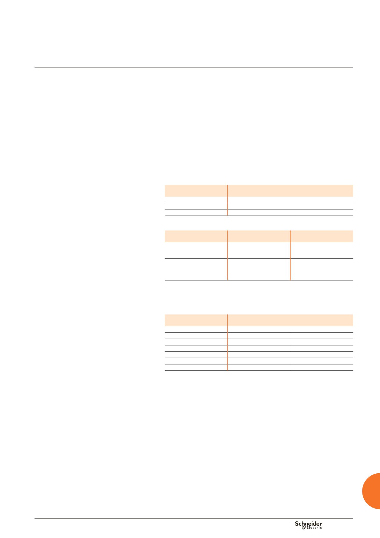
Cable bundles
Cable cross-sectional area
(mm² )
Max. number of cables per bundle
CSA
y
10
8
16 < CSA
y
50
4
CSA
u
50
Tie individually
Tying the cable bundles
Type of tie
Maximum Icw
(kA/rms 1s)
Distance between ties
(mm)
Width: 4.5 mm
Load: 22 kg
10
15
20
200
100
50
Width: 9 mm
Load: 80 kg
20
25
35
45
350
200
100
70
For cable sizes of 50 mm² or more, use 9 mm wide fixing ties.
Recommended tightening torque
for mechanical and electrical connections with
8.8 class screws.
Diameter of screw
Tightening torque (Nm)
(with nut + contact washer)
M3
1.5
M4
3.5
M5
7
M6
13
M8
28
M10
50
M12
75