


 179 / 210

179
Additional information
Electrical characteristics
Designingconnections
y
630A
Device connections
Flexible copper bars with an insulating sheath
Switchboards that comply with standard IEC 61439-1 and 2
It is imperative to use the values indicated below that have been validated for the
installation of devices in Prisma switchboards.
The parameters determining the size of flexible bars are:
b
b
the environment in which the devices are installed:
v
v
position in the enclosure
v
v
dimensions of other conductors in the circuit
v
v
ambient temperature around the switchboard
b
b
the characteristics of the connected devices:
v
v
device heat losses
v
v
the type of installation (horizontal or vertical)
v
v
the type of device (fixed or withdrawable).
Only the equipment manufacturer with in-depth knowledge on:
b
b
the characteristics of the installed devices
b
b
the configuration of the installation in the enclosure can provide the correct sizes
of flexible bars for a given permissible current.
Insulated flexible bars brings flexibility, easy ans quick installation.
Insulated flexible bars are better solution than cables:
b
b
better insulation temperature withstand (125 °C for bars, 105 °C for cables) and a
larger exchange surface for an equivalent size, i.e. a smaller size for a given current
b
b
greater rigidity offering better electrodynamic characteristics for short-circuit
currents
b
b
no intermediate parts (lugs) for a direct connection between the device and the
busbars therefore less temperature rise and less risk of error
b
b
fast implementation of prefabricated connections already cut to length, formed
and drilled.
Technical characteristics
b
b
thickness of the insulation: variable depending on the bar size, 2 mm on average
b
b
rated insulation level Ui = 1000 V
b
b
impulse withstand voltage Uimp = 12 kV
b
b
maximum withstand temperature of insulating material = 125 °C.
Connection
In all enclosures with IP
y
55
b
b
the switchboard internal temperature is 60 °C
b
b
the withstand temperature of the insulating material is 125 °C.
If the withstand temperature of the insulation is only 105 °C, use the next largest
flexible bar.
The bar sizes (S) indicated below take into account the derating curves of devices.
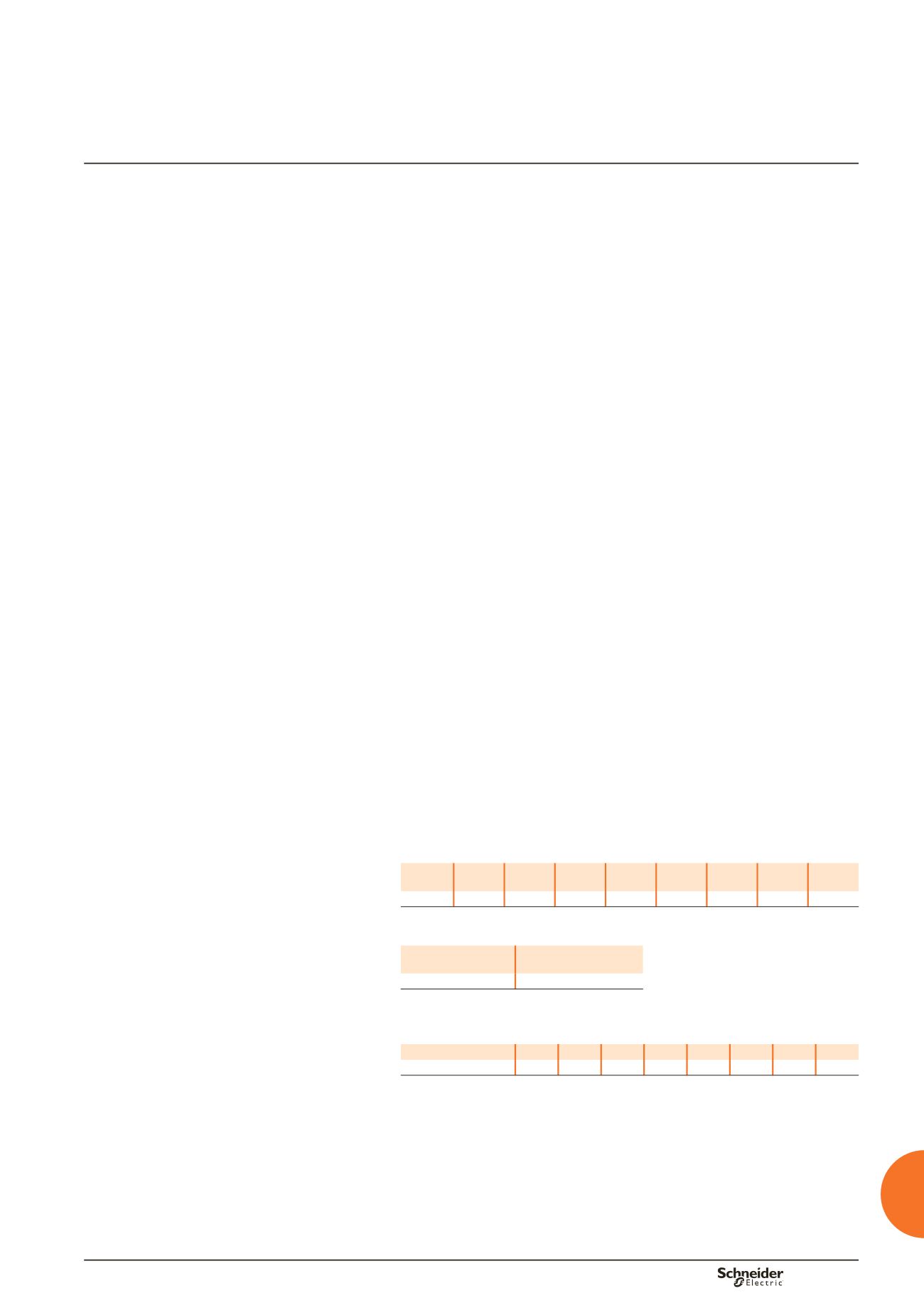
Connection of devices and distribution blocks to busbars
Device INS125 INS160 INS250 INS320
INS400
INS500
INS630
INF250
ISFT250
INF400
ISFT400
INF630
ISFT630
S (mm)
20 x 2 20 x 2 20 x 3 32 x 5
32 x 6 24 x 5
32 x 5
32 x 8
To connect a Compact NSX250 to Linergy BW busbars, use a 24 x 5 mm flexible bar
(04746).
Device
Linergy FM distribution
block (200 A)
S (mm)
20 x 3
Disconnectors, terminal blocks, connections, busbars to
busbars
I max. (60 °C)
200 A 250 A 400 A 400 A 480 A 520 A 580 A 660 A
S (mm)
20 x 2 20 x 3 24 x 5 24 x 5 24 x 6 32 x 5 32 x 6 32 x 8
Note:
the values indicated above have been validated for Prisma switchboards.