


 39 / 182

A-25
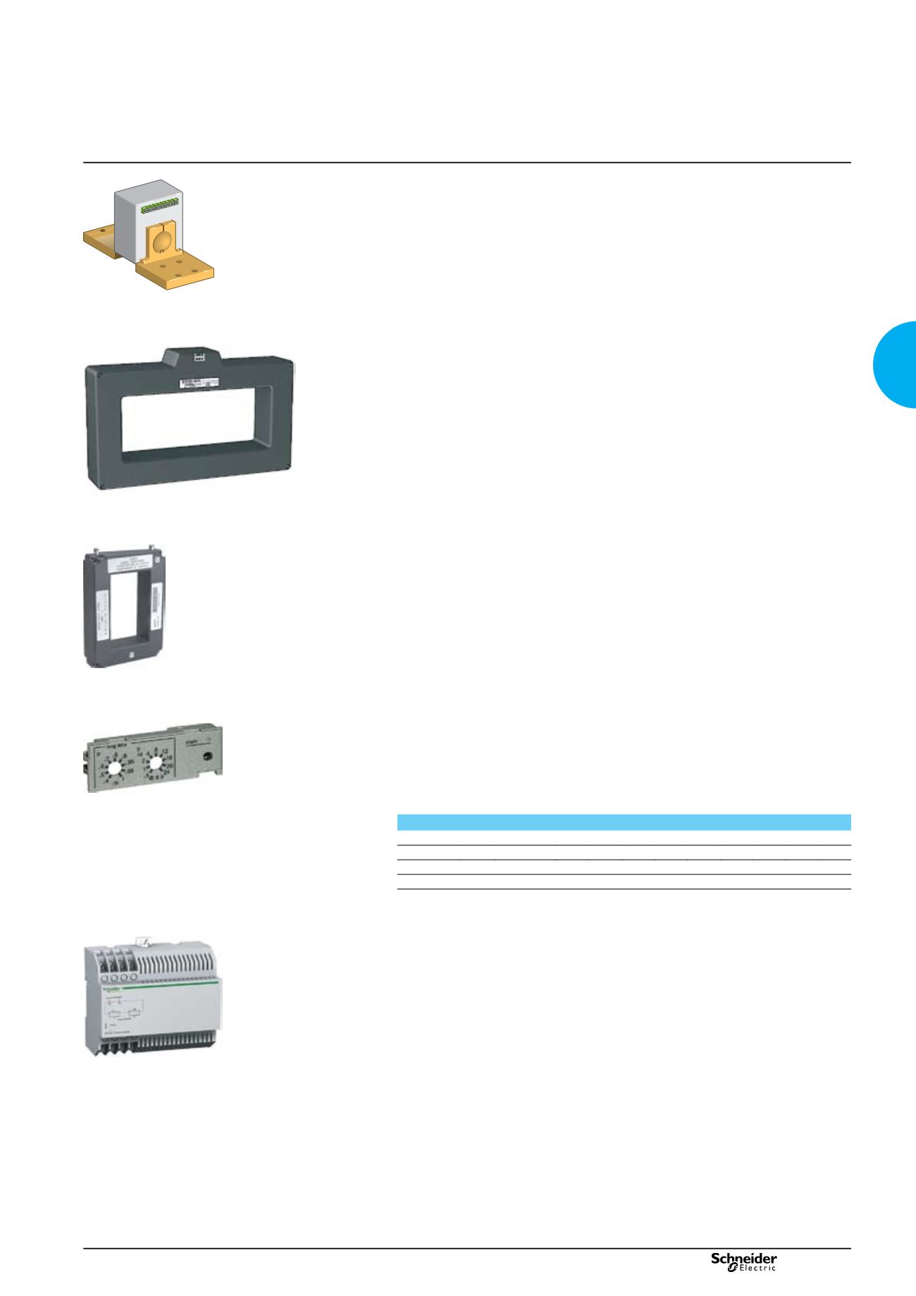
External sensors
External sensor for earth-fault and neutral protection
The sensors, used with the 3P circuit breakers, are installed on the neutral conductor for:
neutral protection (with Micrologic P and H)
b
b
residual type earth-fault protection (with Micrologic A, E, P and H).
b
b
The rating of the sensor (CT) must be compatible with the rating of the circuit breaker:
NT06 to NT16: TC 400/1600
b
b
NW08 to NW20: TC 400/2000
b
b
NW25 to NW40: TC 1000/4000
b
b
NW40b to NW63: TC 4000/6300.
b
b
For oversized neutral protection the sensor rating must be compatible with the
measurement range: 1.6 x IN (available up to NW 40 and NT 16).
Rectangular sensor for earth-leakage protection
The sensor is installed around the busbars (phases + neutral) to detect the zero-
phase sequence current required for the earth-leakage protection. Rectangular
sensors are available in two sizes.
Inside dimensions (mm)
280 x 115 up to 1600 A for Masterpact NT and NW
b
b
470 x 160 up to 3200 A for Masterpact NW.
b
b
External sensor for source ground return protection
The sensor is installed around the connection of the transformer neutral point to earth
and connects to the Micrologic 6.0 control unit via an MDGF module to provide the
source ground return (SGR) protection.
Voltage measurement inputs
Voltage measurement inputs are required for power measurements (Micrologic P
or H) and for earth-leakage protection (Micrologic 7...).
As standard, the control unit is supplied by internal voltage measurement inputs
placed downstream of the pole for voltages between 220 and 690 V AC. On request,
it is possible to replace the internal voltage measurement inputs by an external
voltage input (PTE option) which enables the control unit to draw power directly from
the distribution system upstream of the circuit breaker. An 3 m cable with ferrite
comes with this PTE option.
Long-time rating plug
Four interchangeable plugs may be used to limit the long-time threshold setting
range for higher accuracy.
The time delay settings indicated on the plugs are for an overload of 6 Ir (for further
details, see the characteristics on
page A-13
and
page A-15
).
As standard, control units are equipped with the 0.4 to 1 plug.
Setting ranges
Standard
Ir = In x… 0.4 0.5 0.6 0.7 0.8 0.9 0.95 0.98 1
Low-setting option Ir = In x… 0.4 0.45 0.50 0.55 0.60 0.65 0.70 0.75 0.8
High-setting option Ir = In x… 0.80 0.82 0.85 0.88 0.90 0.92 0.95 0.98 1
Off plug
No long-time protection (Ir = In for Isd setting)
Important:
long-time rating plugs must always be removed before carrying out insulation or
dielectric withstand tests.
External 24 V DC power-supply module
The external power-supply module makes it possible to use the display even if the
circuit breaker is open or not supplied (for the exact conditions of use, see the
“electrical diagrams” part of this catalogue).
This module powers both the control unit (100 mA) and the M2C and M6C
programmable contacts (100 mA).
If the COM communication option is used, the communication bus requires 24 V DC
power supply. With the Micrologic A/E control unit, this module makes it possible to
display currents of less than 20 % of In.
With the Micrologic P and H, it can be used to display fault currents after tripping.
Characteristics
power supply:
b
b
110/130, 200/240, 380/415 V AC (+10 % -15 %)
v
v
24/30, 48/60, 100/125 V DC (+20 % -20 %)
v
v
output voltage: 24 V DC ±5 %, 1 A.
b
b
ripple < 1 % b
b
dielectric withstand : 3.5 kV rms between input/output, for 1 minute
b
b
overvoltage category: as per IEC 60947-1 cat. 4.
b
b
Micrologic control units
Accessories and test equipment
DB101524
External sensor (CT).
PB100834-48
Rectangular sensor.
06133779A
External sensor for source ground return protection.
PB100773-32
Long time rating plug.
PB101026-32A
External 24 V DC power supply module.
version: 10.1
207E2200.indd