


 37 / 182

A-23
Switchboard-display functions
Micrologic A/E/P/H control unit
with COM option (BCM ULP)
Micrologic measurement capabilities come into full play
with the FDM121 switchboard display. It connects to
COM option (BCM ULP) via a breaker ULP cord and
displays Micrologic information. The result is a true
integrated unit combining a circuit breaker and a Power
Meter. Additional operating assistance functions can
also be displayed.
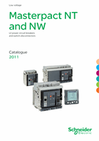
FDM121 switchboard display
The FDM121 switchboard display unit can be connected to a Micrologic COM option
(BCM ULP). It uses the sensors and processing capacity of the Micrologic control
unit. It is easy to use and requires no special software or settings. It is immediately
operational when connected to the COM option (BCM ULP) by a breaker ULP cord.
The FDM121 is a large display, but requires very little depth. The anti-glare graphic
screen is backlit for very easy reading even under poor ambient lighting and at sharp
angles.
Display of Micrologic measurements and trips
The FDM121 is intended to display Micrologic A/E/P/H measurements, trips and
operating information. It cannot be used to modify the protection settings.
Measurements may be easily accessed via a menu.
Trips are automatically displayed.
A pop-up window displays the time-stamped description of the trip and the orange
b
b
LED flashes
Status indications
When the circuit breaker is equipped with the COM option (BCM ULP) (including its
set of sensors) the FDM121 display can also be used to view circuit breaker status
conditions:
O/F: ON/OFF
b
b
SDE: Fault-trip indication (overload, short-circuit, ground fault).
b
b
PF: ready to close
b
b
CH: charged (spring loaded).
b
b
Remote control
When the circuit breaker is equipped with the COM option (BCM ULP) (including its
kit for connection to XF and MX1 communication voltage releases), the FDM121
display can also be used to control (open/close) the circuit breaker. Two operating
mode are available.
local mode : open/close commands are enabled from FDM121 while disable from
b
b
communication network
remote mode : open/close commands are disabled from FDM121 while, enabled
b
b
from communication network.
Main characteristics
96 x 96 x 30 mm screen requiring 10 mm behind the door (or 20 mm when the
b
b
24 volt power supply connector is used).
White backlighting.
b
b
Wide viewing angle: vertical ±60°, horizontal ±30°.
b
b
High resolution: excellent reading of graphic symbols.
b
b
Alarm LED: flashing orange for alarm pick-up, steady orange after operator reset if
b
b
alarm condition persists.
Operating temperature range -10 °C to +55 °C.
b
b
CE / UL / CSAmarking (pending).
b
b
24 V DC power supply, with tolerances 24 V -20 % (19.2 V) to 24 V +10 % (26.4 V).
b
b
When the FDM121 is connected to the communication network, the 24 V DC can be
supplied by the communication system wiring system (see paragraph "Connection").
Consumption 40 mA.
b
b
Mounting
The FDM121 is easily installed in a switchboard.
Standard door cut-out 92 x 92 mm.
b
b
Attached using clips.
b
b
To avoid a cut-out in the door, an accessory is available for surface mounting by
drilling only two 22 mm diameter holes.
The FDM121 degree of protection is IP54 in front. IP54 is maintained after
switchboard mounting by using the supplied gasket during installation.
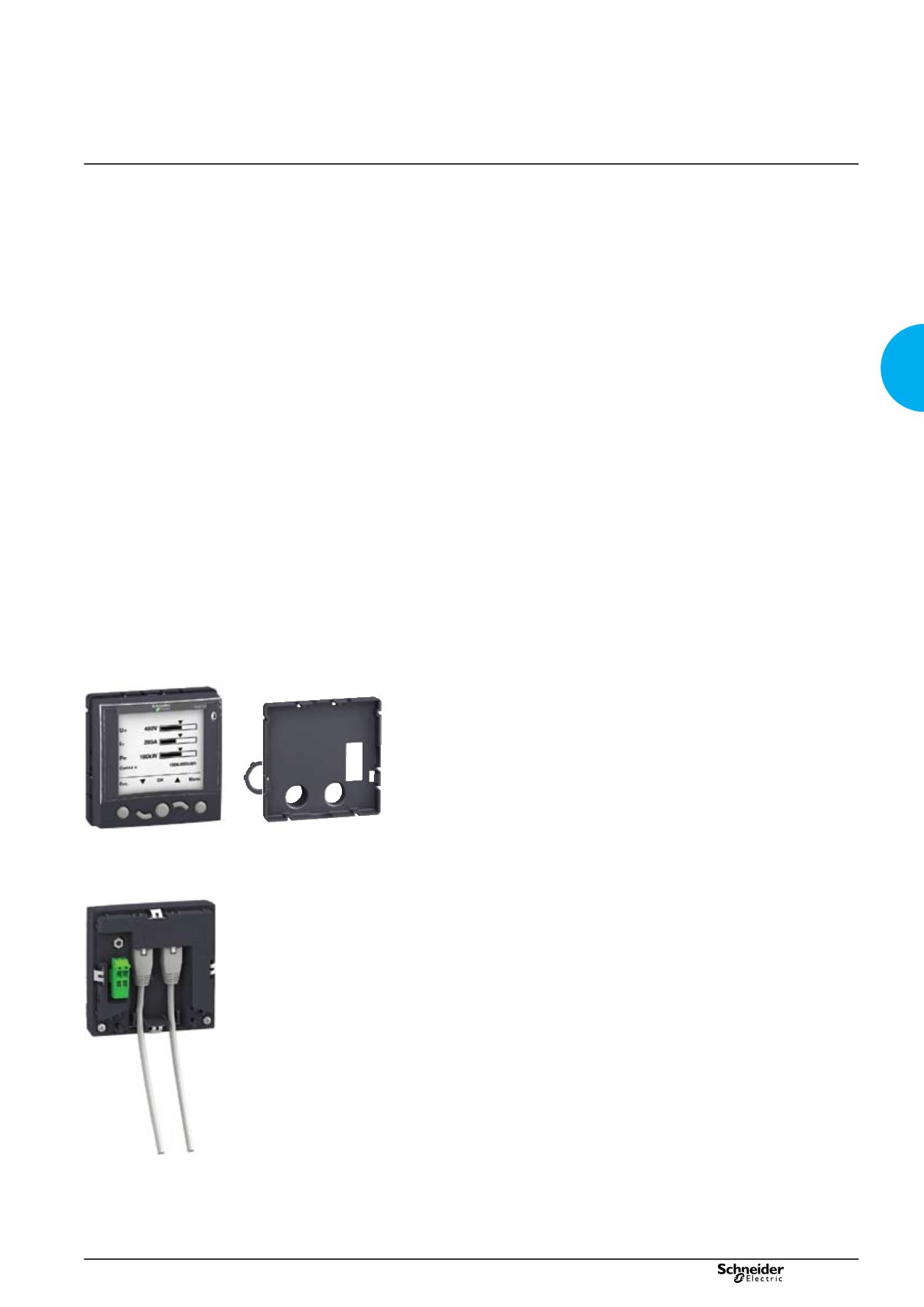
Connection
The FDM121 is equipped with:
a 24 V DC terminal block:
b
b
plug-in type with 2 wire inputs per point for easy daisy-chaining
v
v
power supply range of 24 V DC -20 % (19.2 V) to 24 V DC +10 % (26.4 V).
v
v
A 24 V DC type auxiliary power supply must be connected to a single point on the
ULP system. The FDM121 display unit has a 2-point screw connector on the rear
panel of the module for this purpose. The ULP module to which the auxiliary power
supply is connected distributes the supply via the ULP cable to all the ULP modules
connected to the system and therefore also to Micrologic.
two RJ45 jacks.
b
b
The Micrologic connects to the internal communication terminal block on the
Masterpact via the breaker ULP cord. Connection to one of the RJ45 connectors on
the FDM121 automatically establishes communication between the Micrologic and
the FDM121 and supplies power to the Micrologic measurement functions.
When the second connector is not used, it must be fitted with a line terminator.
PB103582
PB103807-32
FDM121 display.
Surface mount accessory.
PB103581-31
Connection with FDM121 display unit.
version: 10.1
207E2200.indd