


 36 / 182

A-22
Functions
and characteristics
Operating-assistance functions
Micrologic A/E/P/H control unit
with COM option (BCM ULP)
Histories
..................................................................
trip indications in clear text in a number of user-selectable languages
b
b
time-stamping: date and time of trip.
b
b
Maintenance indicators
.........................................
Micrologic control unit have indicators for, among others, the number of operating
cycles, contact wear P/H, load profile and operating times (operating hours counter)
of the Masterpact circuit breaker.
It is possible to assign an alarm to the operating cycle counter to plan maintenance.
The various indicators can be used together with the trip histories to analyse the
level of stresses the device has been subjected to.
Management of installed devices
Each circuit breaker equipped with a COM option (BCM ULP) can be identified via the
communication system:
serial number
b
b
firmware version
b
b
hardware version
b
b
device name assigned by the user.
b
b
This information together with the previously described indications provides a clear
view of the installed devices.
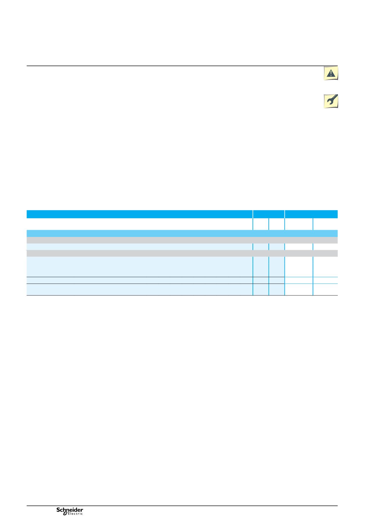
Micrologic A/E/P/H operating assistance functions
Type
Display
A/E P/H Micrologic
LCD
FDM121
display
Operating assistance
Trip history
Trips
Cause of tripping
Ir, Isd, Ii, Ig, I
D
n
-
/E P/H
b
b
Maintenance indicators
Counter
Mechanical cycles
Assignable to an alarm
A/E P/H
-
b
Electrical cycles
Assignable to an alarm
A/E P/H
-
b
Hours
Total operating time (hours)
(1)
A/E P/H
-
-
Indicator
Contact wear
%
- / -
P/H
-
b
Load profile
Hours at different load levels
%
of hours in four current ranges: 0-49 % In, 50-79 %
In, 80-89 % In and
u
90 % In
A
/E P/H
-
b
(1)
Also available via the communication system.
Additional technical characteristics
Contact wear
Each time Masterpact opens, the Micrologic P/H trip unit measures the interrupted current and increments the contact-wear indicator as a function of the
interrupted current, according to test results stored in memory. Breaking under normal load conditions results in a very slight increment. The indicator value may
be read on the FDM121 display. It provides an estimation of contact wear calculated on the basis of the cumulative forces affecting the circuit breaker. When the
indicator reaches 100 %, it is advised to inspect the circuit breaker to ensure the availability of the protected equipment.
Circuit breaker load profile
Micrologic A/E/P/H calculates the load profile of the circuit breaker protecting a load circuit. The profile indicates the percentage of the total operating time at four
current levels (% of breaker In):
0 to 49 % In
b
b
50 to 79 % In
b
b
80 to 89 % In
b
b
u
b
b
90 % In.
This information can be used to optimise use of the protected equipment or to plan ahead for extensions.
version: 10.1
207E2200.indd