


 47 / 248


DB115570
U
S
B or Bluetooth lin
k
Test connector
Displ
a
y
110/
2
40
V
TE
S
T
30
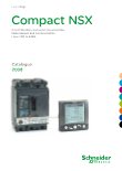
8VLQJ WKH FRQ¿JXUDWLRQ DQG PDLQWHQDQFH PRGXOH
PB103790-20
Test battery (cat. no. LV434206).
PB103833-18
Battery module (cat. no. 54446).
PB103799-24
PB103789-24
24 V DC power-supply
terminal block (cat. no.
LV434210).
NSX cord U > 480 V
(cat. no. LV434204).
PB103803-27
Maintenance case (cat. no. TRV00910).
PB103794-32
&RQ¿JXUDWLRQ DQG PDLQWHQDQFH PRGXOH FDW QR 759
Test battery
This pocket battery connects to the Micrologic test connector. It powers up the
Micrologic and the Ready LED. It supplies the screen and allows settings to be made
via the keypad.
Battery module
The battery module is a back-up supply for the external power-supply module. The
input/output voltages are 24 V DC and it can supply power for approximately three
hours (100 mA).
24 V DC power-supply terminal block
The 24 V DC power-supply terminal block can be installed only on Micrologic 5/6 trip
units. It is required to power the trip unit when the trip unit is not connected to an
FDM121 display unit or to the communication system. When used, it excludes
connection of an NSX cord.
NSX cord
For voltage U
b
y
480 V, available in 3 prefabricated lengths: 0.35 m, 1.3 m and 3 m.
For voltages U > 480 V, a special 0.35 m cord with an insulation accessory is
b
required.
A set of cords with RJ45 connectors is available to adapt to different distances
b
between devices.
Maintenance case
The case includes:
FRQ¿JXUDWLRQ DQG PDLQWHQDQFH PRGXOH
b
power supply (110...220 V AC / 50-60 Hz 24 V DC - 1 A)
b
special cable for connection to the trip-unit test connector
b
standard USB cable
b
standard RJ45 cable
b
user manual
b
optional Bluetooth link (to PC).
b
&RQ¿JXUDWLRQ DQG PDLQWHQDQFH PRGXOH
Included in the maintenance kit, this module tests Micrologic operation and provides
access to all parameters and settings. It connects to the Micrologic test connector
and can operate in two modes.
Stand-alone mode to:
b
supply the Micrologic and check operation via the Ready LED
v
check mechanical operation of the circuit breaker (trip using pushbutton).
v
PC mode, connected to a PC via USB or Bluetooth link. This mode provides
b
access to protection settings, alarm settings and readings of all indicators. Using the
DVVRFLDWHG 568 VRIWZDUH XWLOLW\ LW LV SRVVLEOH WR VWRUH LQ D GHGLFDWHG ¿OH IRU HDFK
device, all the data that can transferred to another device.
This mode also offers operating-test functions:
check on trip time delay (trip curve)
v
check on non-tripping time (discrimination)
v
check on ZSI (Zone Selective Interlocking) function
v
alarm simulation
v
display of setting curves
v
display of currents
v
printing of test reports.
v
559E1400.indd
version: 1.0
A-33