


 312 / 576

312
Spacial SFP
Prisma functional system
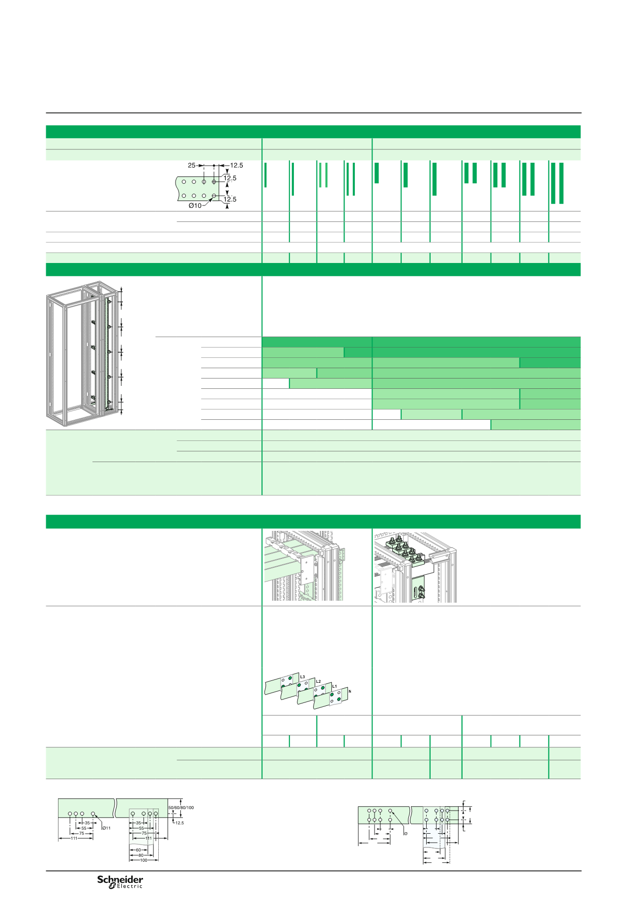
Power busbars
Linergy LGYE - Lateral flat busbars up to 3200 A
Up to 1600 A
Up to 3200 A
In Spacial SFP duct
W300 D500/600/800
W300 D500/600/800
Pre-slotted copper,
1675 mm length
DD381505-LIN-EN.eps
Permissible current for an ambient
temp. of 35 °C around the switchboard
IP
y
31
800 A 1000 A 1400 A 1800 A 1200 A 1400 A 1800 A 2050 A 2300 A 2820 A 3200 A
IP > 31
750 A 900 A 1250 A 1600 A 1080 A 1250 A 1600 A 1850 A 2000 A 2500 A 2820 A
Busbar cross-section (mm)
60 x 5 80 x 5 60 x 5 80 x 5 50 x 10 60 x 10 80 x 10 50 x 10 60 x 10 80 x 10 100 x 10
Number of busbars per phase
1
2
1
2
Cat. no.
04516 04518 04516 04518 04525 04526 04528 04525 04526 04528 04550
(1)
Busbar supports
350mm
max.
100mm
max.
350mm
max.
350mm
max.
350mm
max.
100mm
max.
DD385370.eps
Description
3 fixed supports are compulsory to hold the busbar in position.
If more than 3 supports are needed, use free supports (in addition).
The bottom wedge support is used to place the busbar and ensure it is in the correct position.
It does not count as a busbar support.
Number
of supports
depending
on Icw
(kA rms/1 s)
y
15
3
3
y
25
3+2
3
3
y
30
3+2
3+2
3
y
40
3+4
3+2
3+2
y
50
3+4
3+2
y
60
3+4
3+2
y
65
3+4
3+2
y
75
3+6
3+4
y
85
3+4
Cat. no. of
supports
depending
on distance
between
bars and
duct depth
Spacial SFP duct
75 mm distance
between bars
W300, D500
NSYBVS500
(fixed) +
04662
(free) +
NSYAS500
(spacer)
(2)
W300, D600
NSYBVS600
(fixed) +
04662
(free) +
NSYAS600
(spacer)
(2)
W300, D800
NSYBVS800
(fixed) +
04662
(free) +
NSYAS800
(spacer)
(2)
Spacial SFP duct
115 mm distance
between bars
W300, D800
NSYBVS800L
(fixed) +
04678
(free) +
NSYAS800L
(spacer)
(2)
(1)
Copper bar without holes.
(2)
If using a 100 x 10 bars, add a pack of screws ref.
04671
for each fixed support and free support.
Connections to the Linergy BS horizontal busbar
DD385371.eps
DD385384.eps
Characteristics
For a busbar with 75 mm
distance between bars, the bars
must be completely covered.
Staggered assembly points
between one bar and the next,
to maintain the necessary
clearance distances.
(3)
References
04636
,
04637, 04638
are supplied individually:
1 connection per phase.
Reference
04642
consists of 2 M8 x 140 screws which can
replace the original M8 x 120 screws.
DD383399_modif-LIN.eps
1 vertical bar
per phase
2 vertical bars
per phase
1 vertical bar per phase 2 vertical bars per phase
60 x 5 80 x 5 60 x 5 80 x 5 50 x 10 60 x 10 80 x 10 50 x 10 60 x 10 80 x 10 100 x 10
Cat. no. of the connection piece
depending on horizontal busbar
size
y
80 mm
04645
04636
04637 04637
04645
> 80 mm
04645
04636
+
04642 04637
+
04642
04637
+
04642
04638
+
04642
04645
(3)
Drill hole dimensions for 5 mm thick horizontal busbars.
Drill hole dimensions for 10 mm thick horizontal busbars.
DD385424-EN.eps
50/60/80/100
111
12.5
12.5
100
80
60
111
75
55
35
11
75
55
35
DD384320-LIN-EN.eps