


 276 / 327

Tel
+44 (0)1424 856600
Fax
+44 (0)1424 856611
Technical Hotline
+44 (0)1424 856688
TECHNICAL INFORMATION
Technical information
276 |
PVC-U perimeter trunking systems
Material
PVC-U is flame retardant and self-
extinguishing. It provides a 100%
recyclable material with good
sustainability.
Installation
Positioning
Series R is suitable for dado.
Expansion/contraction
PVC-U expands and contracts at a
uniform rate of approx 5.25mm in
a 3 metre length for a temperature
change of 25°C. Therefore, a 3mm gap
between each length of trunking base
is recommended.
Adequate allowance is made within
the fittings for thermal movement
of the covers, which have a 10mm
overlap on each side.
Fitting
• The base is supplied with pre-cut
elongated holes at 250mm centres.
• Internal couplers on base units are
not required.
• To fasten base, use No 8 round head
screws and washers.
• Avoid over-tightening to permit
thermal movement.
• The use of plastic caps over screw
heads is recommended to protect
installed cables.
• To cut the trunking, use a fine-
toothed panel or power jig-saw.
• External moulded fittings overlap
the joints by up to 10mm to cover
cutting inaccuracies.
• A variable angle jig-saw or chop
saw is recommended for cutting 45
degree mitres.
Single lengths
Where it is required to fit a single
length of trunking (under 3 metres)
between two inside walls and no
accessory box is fitted, it is advisable to
install a coupler in the centre of the run
to facilitate the removal of the cover.
Joints and bends
All base joints should have a 3mm gap
to allow for expansion.
•
Internal bends and external bends:
trunking body must be mitred at
45° to ensure total enclosure of
trunking, including any internal fitted
segregator.
•
Flat angles and tees:
are
prefabricated. Trunking bases should
be cut to butt up to fittings.
Cutting is not critical as the external
moulded clip-on fittings cover the
joints and overlap the trunking covers
by 10mm each side, thus covering any
inaccuracies.
Bend radius control
Please contact the Technical Team on
+44 (0)1424 856688
Accessory boxes
All accessory boxes are mounted
in the main, centre compartment.
The appropriate knockout removal
depends whether supply is to be run in
the centre compartment or either/both
of the outer segregated compartments.
When knockouts are removed, clip
the box into the trunking body. When
boxes are installed consecutively, a
short cut length of centre cover (14mm
min.) is required to cover the space
between boxes.
Covers
The cover has been designed to remain
in position irrespective of impact
during normal conditions, minor
undulations of the mounting surface,
and to limit unauthorised removal.
Covers – fitting
The single cover is clipped into place
from the front. If accessory boxes are
installed, the covers are butt-joined
to the edge of the box (RSSB1/2). The
cut edges the cover are subsequently
concealed by the accessory.
Covers – removal
To remove the cover, first detach a
coupler, internal or external bend
component to gain access. The cover
can then be gently eased off the base.
Method of continuation through
a partition wall
• Continue the main lateral run of base
through the partition wall with short
lengths of cover fitted where the
trunking passes through the partition.
The partition wall trunking is then
butted up to the main run and the
joint covered by an Internal bend.
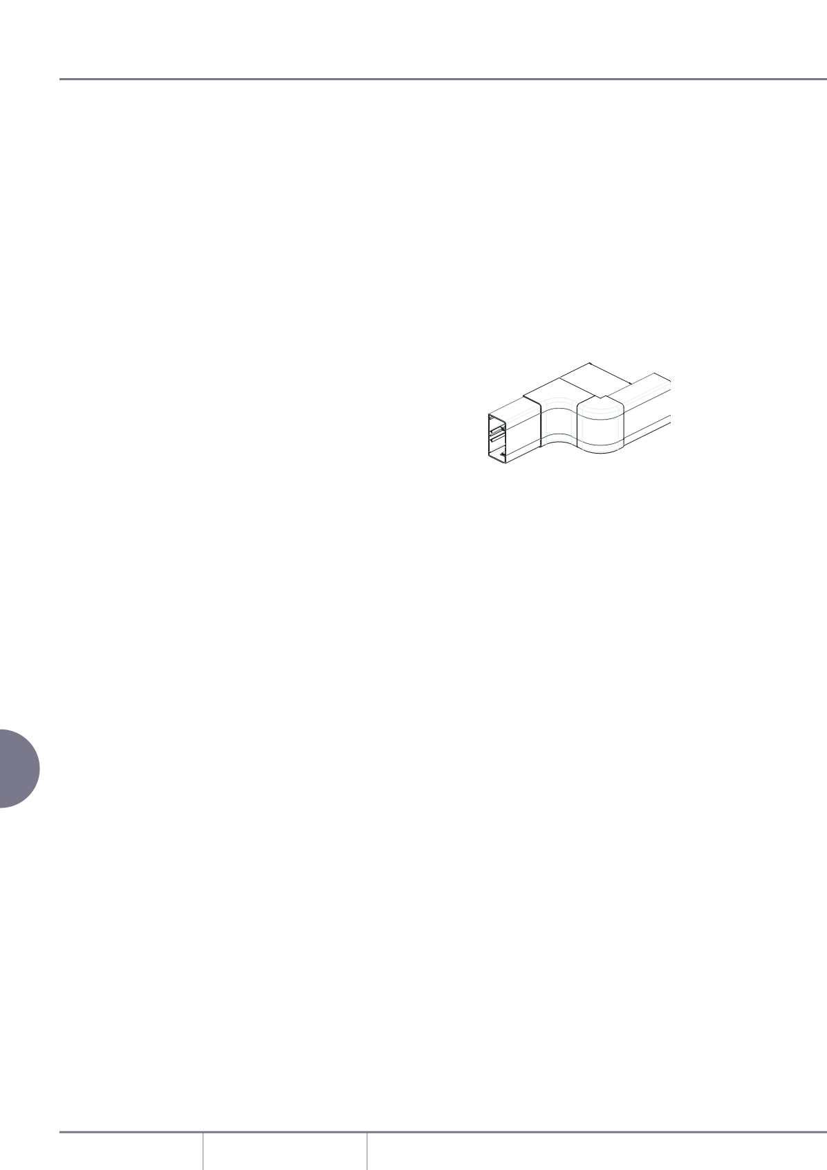
Offset dimensions
The minimum set that can be
accommodated in the same plane
(from internal to external bend), is
shown below.
Series R trunking
155