


 282 / 327

Tel
+44 (0)1424 856600
Fax
+44 (0)1424 856611
Technical Hotline
+44 (0)1424 856688
TECHNICAL INFORMATION
Technical information
282 |
PVC-U perimeter trunking systems
Material
PVC-U is flame retardant and self-
extinguishing. It provides a 100%
recyclable material with good
sustainability.
Installation
Positioning
When used as a skirting system,
sufficient clearance should be allowed
between the floor covering and
the profile fittings that clip over the
cover i.e. 5mm + floor covering is
recommended.
Expansion/contraction
PVC-U expands and contracts at a
uniform rate of approx 5.25mm in
a 3 metre length for a temperature
change of 25°C. Therefore, a 3mm gap
between each length of trunking base
is recommended.
Adequate allowance is made within
the fittings for thermal movement of
the covers, which have a 7mm overlap
on each side.
Fitting
• The base is supplied with pre-cut
elongated holes at 250mm centres.
• Internal couplers on base units are
not required.
• To fasten base, use No 8 round head
screws and washers.
• Avoid over-tightening to permit
thermal movement.
• The use of plastic caps over screw
heads is recommended to protect
installed cables.
• To cut the trunking, use a fine-
toothed panel or power jig-saw.
• External moulded fittings overlap
the joints by up to 10mm to cover
cutting inaccuracies.
• A variable angle jig-saw or chop
saw is recommended for cutting 45°
mitres.
Single lengths
Where it is required to fit a single
length of trunking (under 3 metres)
between two inside walls and no
accessory box is fitted, it is advisable to
install a coupler in the centre of the run
to facilitate the removal of the cover.
Joints and bends
• Base joints should have a 3mm gap
to allow for expansion.
• Internal and external bends: Base
should be cut square to bend base
component.
• Flat angles and tees are
pre-fabricated.
• External moulded fittings overlap the
joints by up to 7mm to cover cutting
inaccuracies.
• End caps to be screw fixed to base.
Bend radius control
The bend radius control fittings for
Twin165 provide a bend radius of
50mm
Accessory boxes
The accessory box is mounted in the
larger compartment (compartment 2). If
supply is from the smaller compartment,
drill the main web adjacent to the box
position. Remove the appropriate knock
out and clip the box into the trunking
base. For boxes supplied from the main
compartment, remove the appropriate
box knock-outs and clip the box into
trunking base. When boxes are installed
consecutively, a 14mmwide spacer (ES1)
is required to cover the space between
the boxes.
• Part M box assemblies with
contrasting coloured faceplates are
available to meet the requirements
of DDA regulations for Visual
Impairment.
Covers
The covers have been designed to
remain in position irrespective of
impact during normal conditions, minor
undulations of the mounting surface,
and to limit unauthorised removal.
Covers – fitting
Covers are clipped into place from the
front. If accessory boxes are installed, the
covers are butt-joined to the edge of the
box. For the fitting of couplers, a gap of
25mm is left between the two cover ends.
Covers – removal
To remove a cover, first detach a
coupler, internal or external bend
component to gain access. Both covers
can then be gently eased off the base.
Screening
Special conductive spray coating can
be applied to one compartment, the
cover, accessory boxes and fittings,
to screen data cables against EMI
interference.
•
For data/voice circuits only:
Warning: Owing to its relatively
high surface resistance, CS coating
SHOULD NOT be in contact with low
voltage circuits BS7671 (1992) 50
V.A.C. – 1000 V.A.C. unless additional
measures are undertaken.
• Part M box assemblies with
contrasting coloured faceplates are
available to meet the requirements
of DDA regulations for Visual
Impairment.
Antimicrobial
For technical details of antimicrobial
Twin165 Bio trunking, please refer to
Laboratory and Healthcare section.
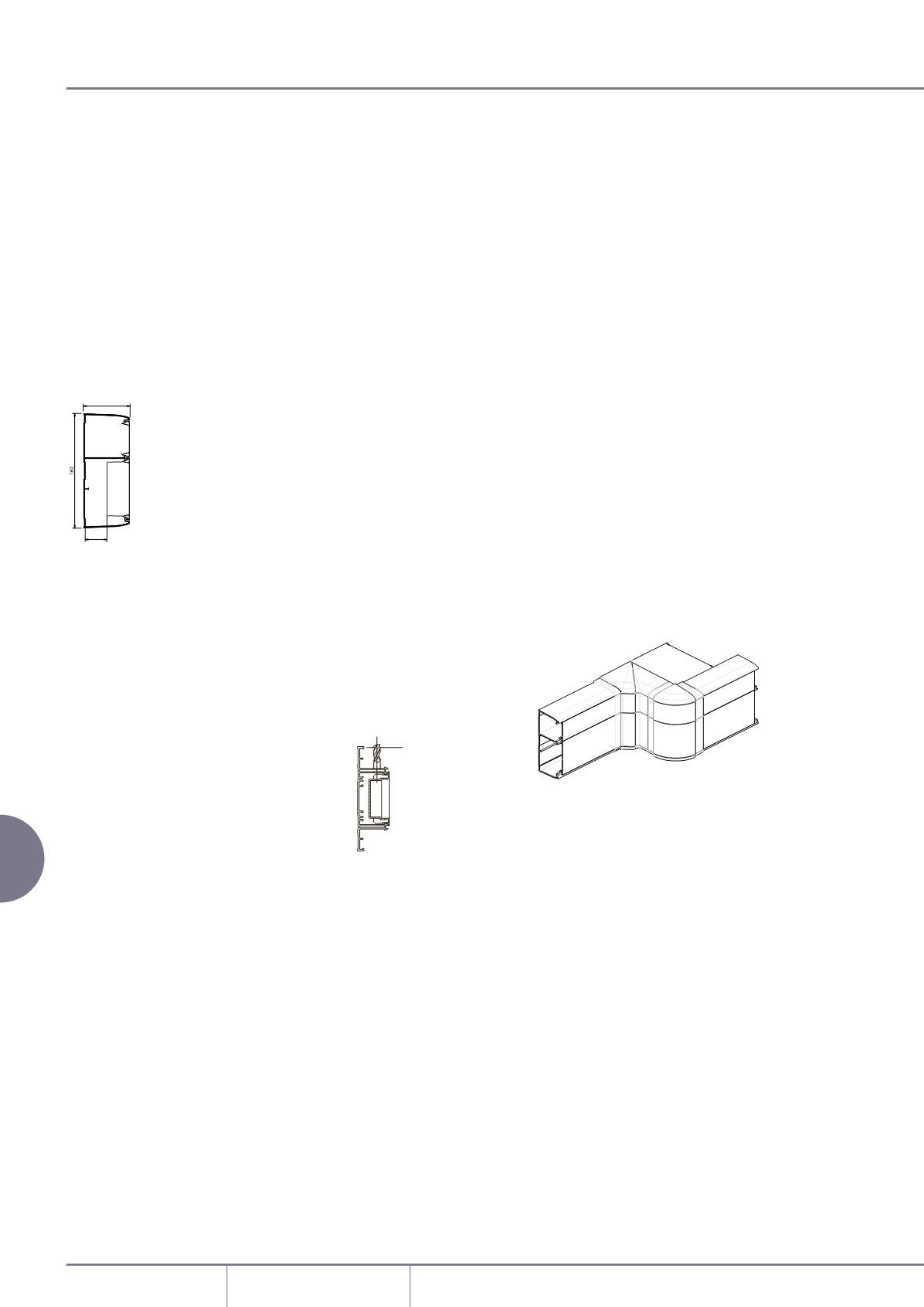
Offset dimensions
The minimum set that can be
accommodated in the same plane
(from internal to external bend), is
shown below.
Twin165 trunking
MIN
90mm
5mm +
FLOOR
COVERING
STERLING COMPACT
AND PROFILE
DRILL HOLE OF
SUITABLE SIZE
143mm