


 167 / 210

167
Note : Through entry boxes provide extra wiring space but not looping
terminals
n
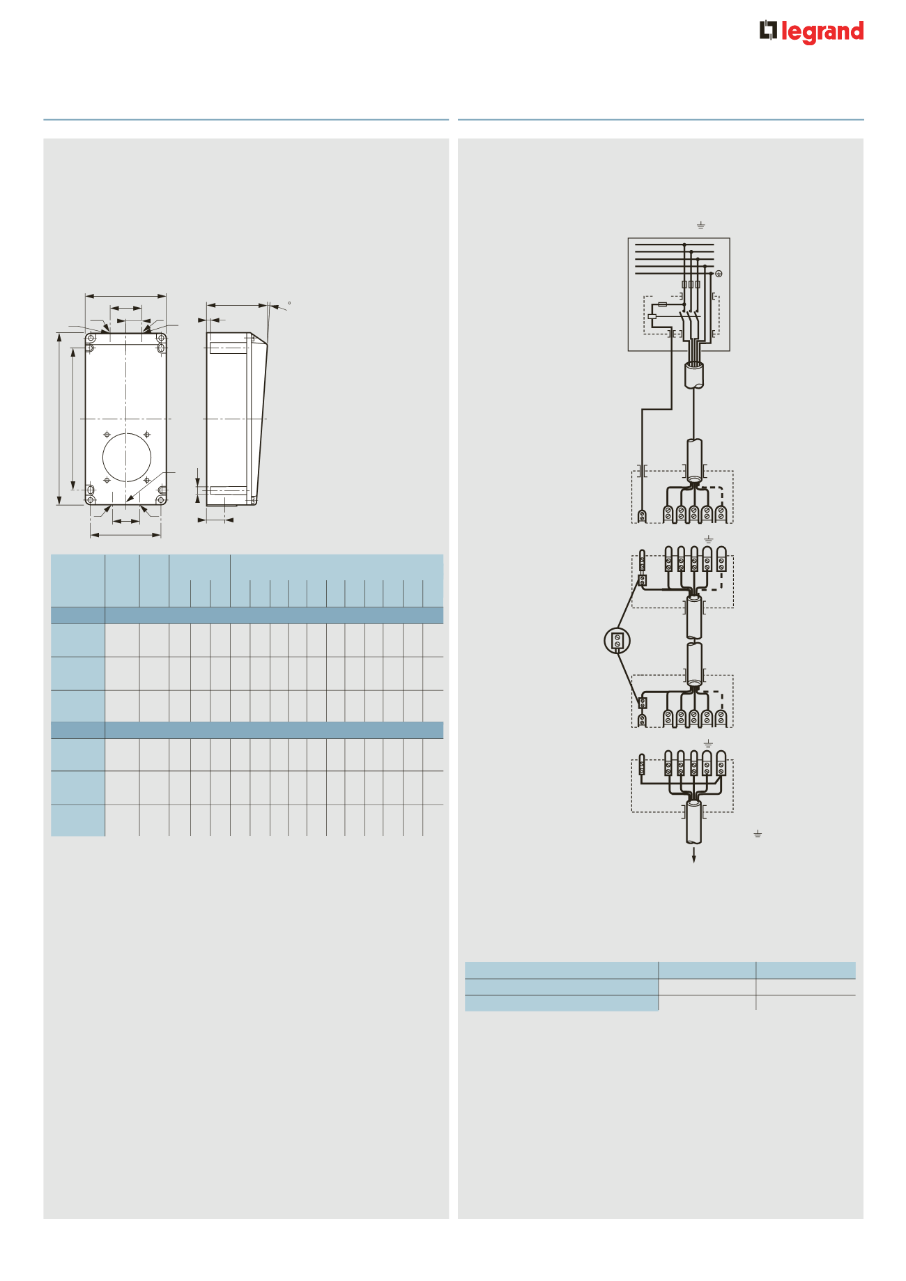
Dimensions
Reversible boxes for surface mounting
LV 16 to 32 A
(p. 163-164)
D
F
X
Z
C
A
B
X
E
I
G
5
K
H
Y
Y
Y
J
X
052929-58933c.eps
Back
boxes
Material Weight Fixings (mm)
Dimensions (mm)
Panel
(kg) A B H C D E F G I
J K X Y Z
mounting
sockets
16 A
2 P +
T
Plastic 0·330 145 74 5·3 182 86 22 34 75 4 – – – M20 –
3 P +
T
Plastic 0·330 145 74 5·3 182 86 22 34 75 4 – – – M20 –
3 P + N +
T
Plastic 0·330 145 74 5·3 182 86 22 34 75 4 – – – M20 –
32 A
2 P +
T
Plastic 0·670 234 117 5·3 270 130 30 50 110 4 – – – M25 –
3 P +
T
Plastic 0·670 234 117 5·3 270 130 30 50 110 4 – – – M25 –
3 P + N +
T
Plastic 0·670 234 117 5·3 270 130 30 50 110 4 – – – M25 –
➞
➞
Plastic box equipped with :
- 2 internal linked earth terminals
3 P + N +
Coil
Fuse
Contactor
Pilot
L1 L2 L3
N
Socket outlet
Plug
L1
L2
L3
N
Mobile socket
Appliance inlet
Pilot
L1 L2 L3
N
3 P + N +
053582-64561s.eps
To equipment
n
Example of 63 A 3 P +
T
and 3 P + N +
T
pilot pin
connection
The pilot pin enables the load to be removed prior to the separation of
the phase pins, when the circuit is routed via a contactor
The pilot pin connection accepts 2·5-6 mm
2
flexible or up to 10 mm
2
rigid conductor. It is the small centre pin in the connection
n
Technical information
IK 09 (plastic) according to BS EN 62262 and IEC 62262
Contacts : nickel plated brass with stainless steel connection pins
n
Pilot cabling
63 A
Conductors type
Plugs and mobile sockets
2 . 5 to 6
Flexible
Surface and panel mounting sockets
2 . 5 to 10
Rigid
Hypra
®
IP 44 - LV 16/32 A
t
hrough entry surface mounting boxes
Hypra
®
IP 44 - LV 63 A
p
ilot pin connection