


 173 / 210

173
Note : Through entry boxes provide extra wiring space but not looping terminals
Through entry surface mounting boxes
Reversible boxes for surface mounting through entry sockets
LV 16 to 63 A
(p. 169-170)
➞
Plastic box equipped with :
- 2 internal linked earth terminals
3 P + N +
Coil
Fuse
Contactor
Pilot
L1 L2 L3
N
Socket outlet
Plug
L1
L2
L3
N
Mobile socket
Appliance inlet
Pilot
L1 L2 L3
N
3 P + N +
053582-64561s.eps
To equipment
n
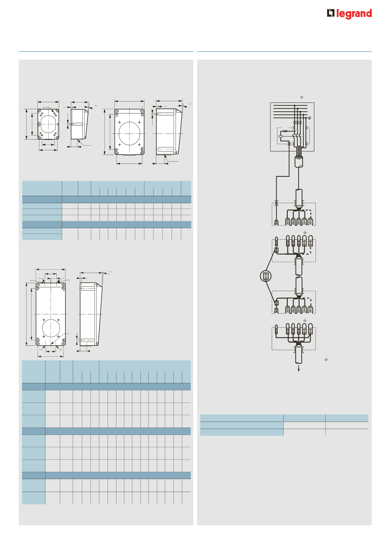
Example of 63/125 A 3 P +
T
and 3 P + N +
T
pilot pin
connection
The pilot pin enables the load to be removed prior to the separation of
the phase pins, when the circuit is routed via a contactor
Back boxes
Material
Weight
Fixings (mm)
Dimensions (mm)
C.E.
Panel mounting
(kg) A1 A2 ød A A3 ØT B C D E
sockets
LV 16 A
2 P +
T
Plastic 0·115 51 68 4·2 64 – 5·3 74 106 58 20 M 20
3 P +
T
Plastic 0·160 68 68 4·2 85 – 5·3 96 122 60 22 M 20
3 P + N +
T
Plastic 0·160 68 68 4·2 85 – 5·3 96 122 60 22 M 20
LV 32 A
2 P +
T
/ 3 P +
T
3 P + N +
T
Plastic 0·340 –
– – 90 125 5·3 102 162 90 26 M 25
➞
➞
n
Dimensions
Surface mounting boxes
Reversible boxes for surface mounting sockets
Boxes can be rotated to aid entry
LV 16 A
(p. 169)
C
A2
B
A
C.E.
D
4
5
E
ØT
A1
Ø d
052419-52465c.eps
C
A2
B
A
C.E.
D
4
5
E
ØT
A1
Ø d
052419-52465c.eps
A1 and A2 : optional blind fixing points
Metal boxes are equipped with :
- 2 internal linked earth terminals and 1 external earth terminal
- 1 tulip earth pin connection between base and cover
C
A3
B
A
D
4
5
E
ØT
C.E.
052929-52467c.eps
C
A3
B
A
D
4
5
E
ØT
C.E.
052929-52467c.eps
D
F
X
Z
C
A
B
X
E
I
G
5
K
H
Y
Y
Y
J
X
052929-58933c.eps
Back
boxes
Material Weight Fixings (mm)
Dimensions (mm)
Panel
(kg) A B H C D E F G I
J K X Y Z
mounting
sockets
16 A
2 P +
T
Plastic 0·330 145 74 5·3 182 86 22 34 75 4 – – – M20 –
3 P +
T
Plastic 0·440 175 88 5·3 212 100 22 40 77 4 – – – M20 –
3 P + N +
T
Plastic 0·440 175 88 5·3 212 100 22 40 77 4 – – – M20 –
32 A
2 P +
T
Plastic 0·670 234 117 5·3 270 130 30 50 120 4 – – – M25 –
3 P +
T
Plastic 0·670 234 117 5·3 270 130 30 50 120 4 – – – M25 –
3 P + N +
T
Plastic 0·670 234 117 5·3 270 130 30 50 120 4 – – – M25 –
63 A
3 P +
T
Plastic 2·000 260 152 6·3 300 170 40 – 150 8 50 70 M32 – M20
3 P + N +
T
Plastic 2·000 260 152 6·3 300 170 40 – 150 8 50 70 M32 – M20
LV 32 A
(p. 170)
The pilot pin connection accepts 2·5-6 mm
2
flexible or up to 10 mm
2
rigid conductor. It is the small centre pin in the connection
n
Pilot cabling
63 A
Conductors type
Plugs and mobile sockets
2 . 5 to 6
Flexible
Surface and panel mounting sockets
2 . 5 to 10
Rigid
➞
➞
Hypra
®
IP 66/67-55 - LV 16/32/63 A
s
urface mounting and through entry back boxes
Hypra
®
IP 66/67-55 - LV 63 and 125 A
p
ilot pin connection