


 166 / 210

166
n
Dimensions
Reversible boxes for surface mounting sockets
Boxes can be rotated to aid entry
ELV 16 A , LV 16 A
(p. 163)
C
A2
B
A
C.E.
D
4
5
E
ØT
A1
Ø d
052419-52465c.eps
A1 and A2 : optional blind
fixing points
Metal boxes are equipped with :
- 2 internal linked earth terminals
and 1 external earth terminal
- 1 tulip earth pin connection
between base and cover
LV 32 A
(p. 164)
C
A3
B
A
D
4
5
E
ØT
C.E.
052929-52467c.eps
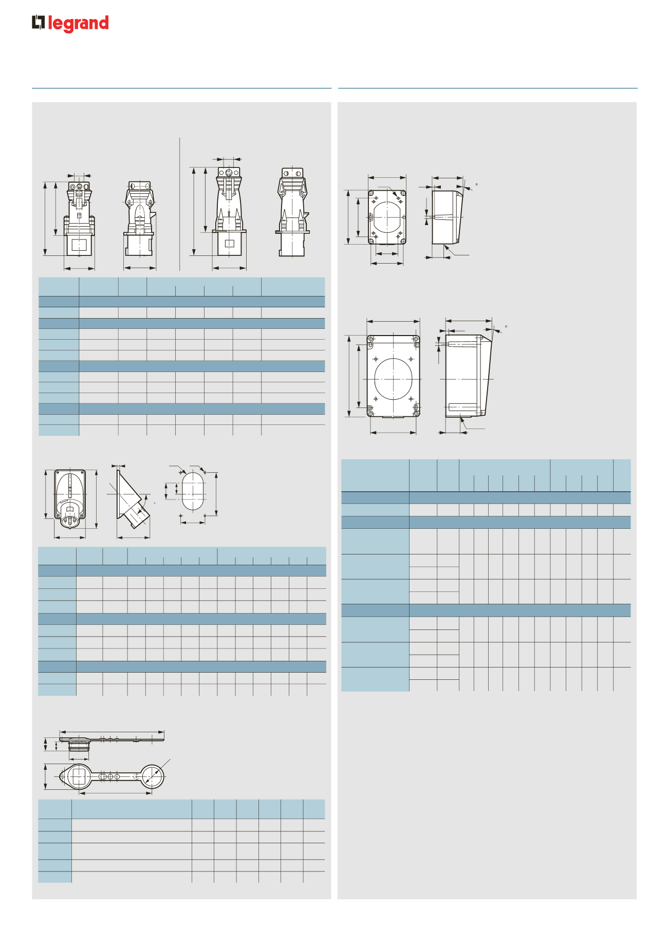
Back boxes
Material
Weight
Fixings (mm)
Dimensions (mm) C.E.
Panel mounting
(kg) A1 A2 Ød A A3 ØT B C D E
sockets
ELV 16 A/32 A
2 P
Plastic 0·115 51 68 4·2 64 – 5·3 74 106 58 20 M 25
LV 16 A
2 P +
T
Plastic 0·115 51 68 4·2 64 – 5·3 74 106 58 20 M 20
3 P +
T
Plastic 0·160
68 68 4·2 85 – 5·3 96 122 60 22 M 20
Metal 0·520
3 P + N +
T
Plastic 0·160
68 68 4·2 85 – 5·3 96 122 60 22 M 20
Metal 0·520
LV 32 A
2 P +
T
Plastic 0·340
–
– – 90 125 5·3 102 162 90 26 M 25
Metal 0·910
3 P +
T
Plastic 0·340
–
– – 90 125 5·3 102 162 90 26 M 25
Metal 0·910
3 P + N +
T
Plastic 0·340
–
– – 90 125 5·3 102 162 90 26 M 25
Metal 0·910
➞
➞
A1 and A2 : optional blind
fixing points
Metal boxes are equipped with :
- 2 internal linked earth terminals
and 1 external earth terminal
- 1 tulip earth pin connection
between base and cover
Hypra
®
IP 44 - ELV 16 A and LV 16/32/63 A
m
etal and plastic plugs and sockets (continued)
Hypra
®
IP 44 - ELV 16 A and LV 16/32 A
s
urface mounting back boxes
Panel appliance inlets IP 44
1
(p. 163-164)
Appliance inlet covers
(p. 163-164)
16/32/63 A
Ø D Ø T
A
B
G
H
I
50
D
C
E
F
Material
Weight
Drilling (mm)
Dimensions (mm)
(kg)
A
B ØT ØD G
H
C
D
E
F
I
LV 16 A
2 P +
T
Plastic 0·140 94 62 4·5 40
–
– 104 72 121 78
6
3 P +
T
Plastic 0·160 109 83 4·5 40
–
– 120 94 135 86
6
3 P + N +
T
Plastic 0·190 109 83 4·5 40
–
– 120 94 139 86
6
LV 32 A
2 P +
T
Plastic 0·280 149 90 5·5 40
–
– 160 101 176 111
6
3 P +
T
Plastic 0·280 149 90 5·5 40
–
– 160 101 176 111
6
3 P + N +
T
Plastic 0·320 149 90 5·5 40
–
– 160 101 174 108
6
LV 63 A
3 P +
T
Plastic 0·630 163 93 6·5 80 42 62 183 113 221 120
8
3 P + N +
T
Plastic 0·690 163 93 6·5 80 42 62 183 113 221 120
8
Cat. Nos.
Product
Ø A Ø B
C
D
E
F
(mm) (mm) (mm) (mm) (mm) (mm)
0521 25
16 A – 2 P +
T
38
50
26
18
140 200
0521 26
16 A – 3 P +
T
43
55
26
18
150 215
16 A – 3 P+N+
T
0521 27
32 A – 2 P+
T
, 3 P +
T
50
62
26
18
160 232
0527 99
32 A – 3 P+N+
T
56
68
26
18
167
248
0536 99
63 A – 3 P +
T
, 3 P+N+
T
62
74
26
18
205
290
c052125
Ø A
Ø A
Ø B
D
C
E
F
n
Dimensions (continued)
Straight plugs IP 44
ELV 16 A, LV 16/32 A
(p. 163-164)
LV 63 A
(p. 164)
D
Ø
A
B
C
051942-4380c.eps
A
B
D
Ø
053542-52332c.eps
Material
Weight
Dimensions (mm)
Ø Clamping
(kg)
A
B
C
D
and grip (mm)
ELV 16 A
2 P
Plastic
0·180
142
107
62
55
8·5 to 22
LV 16 A
2 P +
T
Plastic
0·150
135
100
57
55
8 to 15
3 P +
T
Plastic
0·175
139
103
65
60
8 to 15
3 P + N +
T
Plastic
0·210
154
118
73
66
10 to 18
LV 32 A
2 P +
T
Plastic
0·260
164
119
78
70·5
10 to 18
3 P +
T
Plastic
0·260
164
119
78
70·5
12 to 22
3 P + N +
T
Plastic
0·300
170
125
86
77
12 to 22
LV 63 A
3 P +
T
Plastic
0·640
255
188·5
–
102
18·5 to 29
3 P + N +
T
Plastic
0·700
255
188·5
–
102
20·5 to 32
1 : Wiring diagram for 63 A shown on p. 167