
30
MR
medium rating busbar
medium power 160 - 1000 A
Pack
Cat. Nos.
Trunking lengths –
bespoke dimensions
Please specify required length
when ordering
(see p. 49 – how to measure
bespoke dimensions)
1 501 to 2999 mm lengths with
2 + 2 outlets
Tap-off outlets in fixed position on
both sides
Aluminium
Copper
Rating (A)
1
504
0
0151
160
1
504
0
0152 554
0
0152
250
1
504
0
0153 554
0
0153
315
1
504
0
0154 554
0
0154
400
1
504
0
0158
500
1
504
0
0155 554
0
0155
630
1
504
0
0156 554
0
0156
800
1
504
0
0157
1
554
0
0157 1 000
1501 to 2999 mm lengths
without outlets
Feeder lengths. A tap-off point
is only possible on the junction
between two lengths
(see bolt-on tap-off boxes p. 41)
Rating (A)
1
504
0
0121
160
1
504
0
0122 554
0
0122
250
1
504
0
0123 554
0
0123
315
1
504
0
0124 554
0
0124
400
1
504
0
0128
500
1
504
0
0125 554
0
0125
630
1
504
0
0126 554
0
0126
800
1
504
0
0127
1
554
0
0127 1 000
Pack
Cat. Nos.
Trunking lengths – 3 m
For vertical runs or riser
applications. Special lengths
between 400 mm and 3 m are
available upon request
With 3 + 3 outlets
Tap-off outlets are spaced every
1·0 m on both sides (6 positions
per 3 m length)
Weight (kg)
Aluminium
Copper
Rating (A)
Aluminium Copper
1
504
0
0101
160
19·9
–
1
504
0
0102 554
0
0102
250
20·9
25·7
1
504
0
0103 554
0
0103
315
22·8
28·1
1
504
0
0104 554
0
0104
400
33·8
36·9
1
504
0
0108
500
37·5
–
1
504
0
0105 554
0
0105
630
41·7
56·0
1
504
0
0106 554
0
0106
800
44·3
72·1
1
504
0
0107
1
554
0
0107 1 000
46·8
83·7
With 5 outlets on one side
Suitable for rising mains
(see p. 50)
Weight (kg)
Rating (A)
Aluminium Copper
1
504
0
0251
160
19·9
–
1
504
0
0252 554
0
0252
250
20·9
25·7
1
504
0
0253 554
0
0253
315
22·8
28·1
1
504
0
0254 554
0
0254
400
33·8
36·9
1
504
0
0258
500
37·5
–
1
504
0
0255 554
0
0255
630
41·7
56·0
1
504
0
0256 554
0
0256
800
44·3
72·1
1
504
0
0257
1
554
0
0257 1 000
46·8
83·7
Without outlets
Feeder lengths. A tap-off point
is only possible on the junction
between two lengths
(see bolt-on tap-off boxes p. 41)
Weight (kg)
Rating (A)
Aluminium Copper
1
504
0
0241
160
19·9
–
1
504
0
0242 554
0
0242
250
20·9
25·7
1
504
0
0243 554
0
0243
315
22·8
28·1
1
504
0
0244 554
0
0244
400
33·8
36·9
1
504
0
0248
500
37·5
–
1
504
0
0245 554
0
0245
630
41·7
56·1
1
504
0
0246 554
0
0246
800
44·3
72·1
1
504
0
0247
1
554
0
0247 1 000
46·8
83·7
IP 55 (according to BS EN 60529)
Flame retardant in compliance with IEC 60332-3. Fully compliant with BS EN 60439-2
Rated currents are at an average ambient temperature of 40° C (over and above the required standard of 35° C)
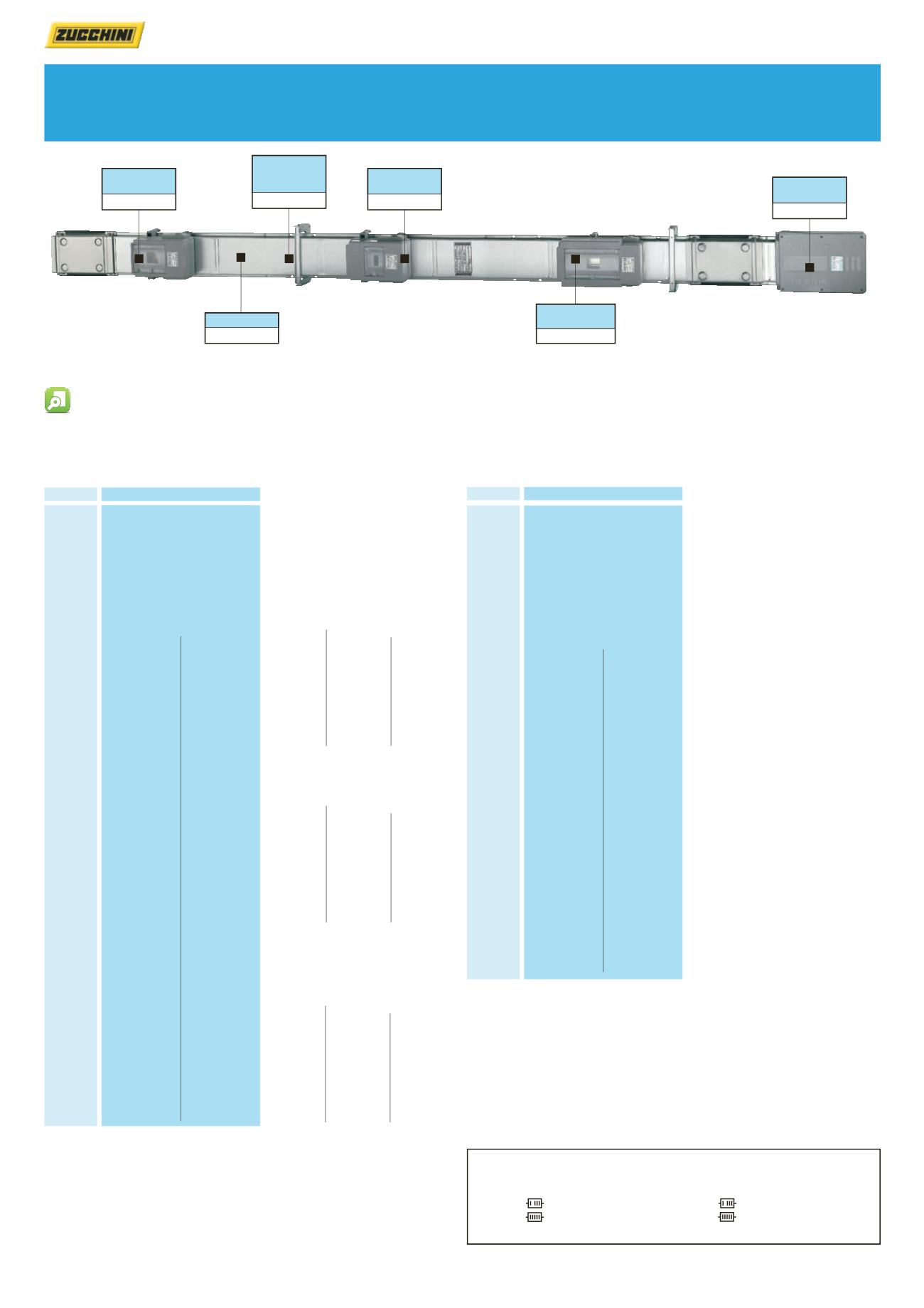
End feed unit (see p. 37) 50401102 Tap-off box (see p. 39) 50414063 Tap-off box (see p. 39) 50414064 Suspension bracket (see p. 42) 50632001 Tap-off box (see p. 39) 50414075Trunking length
50400102
Key : How to select the correct configuration and finish
All examples on this page show 4 conductor galvanised lengths
No. of conductors and finish is dictated by the
red
number
0
= 4 conductors. Galvanised
2
= 4 conductors. Painted
1
= 5 conductors. Galvanised
3
= 5 conductors. Painted
Replace
0
with
1
,
2
, or
3
if required
4
5
- - -
0
- - - -
- - -
1
- - - -
- - -
2
- - - -
- - -
3
- - - -
Codes table
Conductors Case
Code
Painted
Painted
Galvanized
Galvanized
MR
MRF
MR-P
MRF-P
-
-
t l
t
i t
i ted
l
i
l
i
P
4
5
- - -
0
- - - -
- - -
1
- - - -
- - -
2
- - - -
- - -
3
- - - -
Codes table
Conductors Case
Code
Painted
Painted
Gal nized
Galvanized
MR
MRF
MR-P
MRF-P
-
-
-
t l
n t r
P i t
i t
l
i
G l
i
-
-
1 : The 1 000 A aluminium is
supplied painted as standard
Dimensions and technical information p. 43 Measuring bespoke dimensions p. 49 Technical data p. 52-56


