
37
MR
medium rating busbar
feed units
MR is fully compliant with BS EN 60439-2
Rated currents are at an average ambient temperature of 40° C (over and above the required standard of 35° C)
IP 55 (according to BS EN 60529)
Pack
Cat. Nos.
Feed units
Metal end feed units
For plates and hole dimensions
refer to switchboard-transformer
feed units with same rating (p. 38)
Left end
Weight (kg)
Aluminium
Copper
Rating (A)
Aluminium
Copper
1
504
0
1131
160
17·74
–
1
504
0
1132
554
0
1132
250
17·76
18·47
1
504
0
1133
554
0
1133
315
17·83
18·70
1
504
0
1134
554
0
1134
400
23·22
19·58
1
504
0
1138
500
23·20
–
1
504
0
1135
554
0
1135
630
23·63
26·07
1
504
0
1136
554
0
1136
800
23·70
27·80
1
504
0
1137
554
0
1137
1 000
24·00
29·03
Right end
Weight (kg)
Rating (A)
Aluminium
Copper
1
504
0
1121
160
16·64
–
1
504
0
1122
554
0
1122
250
16·76
17·37
1
504
0
1123
554
0
1123
315
17·03
17·70
1
504
0
1124
554
0
1124
400
18·32
18·88
1
504
0
1128
500
20·00
–
1
504
0
1125
554
0
1125
630
19·43
21·17
1
504
0
1126
554
0
1126
800
19·80
23·30
1
504
0
1127
554
0
1127
1 000
20·20
24·83
Plastic end feed units
Terminals accept cables up to
150 mm
2
. For higher ratings attach
cable lugs to spreaders provided
Left end
Weight (kg)
Aluminium
Copper
Rating (A)
Aluminium
Copper
1
504
0
1111
160
6·80
–
1
504
0
1112
554
0
1112
250
6·85
7·20
Right end
Weight (kg)
Rating (A)
Aluminium
Copper
1
504
0
1101
160
5·70
–
1
504
0
1102
554
0
1102
250
5·85
6·10
Pack
Cat. Nos.
Feed units
(continued)
End feed unit with AC23 switch
disconnector
This feed unit allows isolation of
the line for maintenance
Right end up
Weight (kg)
Aluminium
Copper
Rating (A)
Aluminium
Copper
1
504
0
3401
160
17·94
–
1
504
0
3402
554
0
3402
250
18·10
19·12
1
504
0
3403
554
0
3403
315
18·86
19·40
1
504
0
3404
554
0
3404
400
21·79
20·34
1
504
0
3408
500
22·42
–
1
504
0
3405
554
0
3405
630
23·64
26·88
1
504
0
3406
554
0
3406
800
24·95
28·67
1
504
0
3407
554
0
3407
1 000
26·50
29·95
Right end down
Weight (kg)
Rating (A)
Aluminium
Copper
1
504
0
3411
160
17·94
–
1
504
0
3412
554
0
3412
250
18·10
19·12
1
504
0
3413
554
0
3413
315
18·86
19·40
1
504
0
3414
554
0
3414
400
21·79
20·34
1
504
0
3418
500
22·42
–
1
504
0
3415
554
0
3415
630
23·64
26·88
1
504
0
3416
554
0
3416
800
24·95
28·67
1
504
0
3417
554
0
3417
1 000
26·50
29·95
Left end up
Weight (kg)
Rating (A)
Aluminium
Copper
1
504
0
3421
160
17·94
–
1
504
0
3422
554
0
3422
250
18·10
19·12
1
504
0
3423
554
0
3423
315
18·86
19·40
1
504
0
3424
554
0
3424
400
21·79
20·34
1
504
0
3428
500
22·42
–
1
504
0
3425
554
0
3425
630
23·64
26·88
1
504
0
3426
554
0
3426
800
24·95
28·67
1
504
0
3427
554
0
3427
1 000
26·50
29·95
Left end down
Weight (kg)
Rating (A)
Aluminium
Copper
1
504
0
3431
160
17·94
–
1
504
0
3432
554
0
3432
250
18·10
19·12
1
504
0
3433
554
0
3433
315
18·86
19·40
1
504
0
3434
554
0
3434
400
21·79
20·34
1
504
0
3438
500
22·42
–
1
504
0
3435
554
0
3435
630
23·64
26·88
1
504
0
3436
554
0
3436
800
24·95
28·67
1
504
0
3437
554
0
3437
1 000
26·50
29·95
End stops
Ensure IP 55 protection at the end
of the run
For right and left feed units
1
50403101
160 – 315 A - for aluminium
250 – 400 A - for copper
1
50403102
400 – 1000 A - for aluminium
630 – 1000 A - for copper
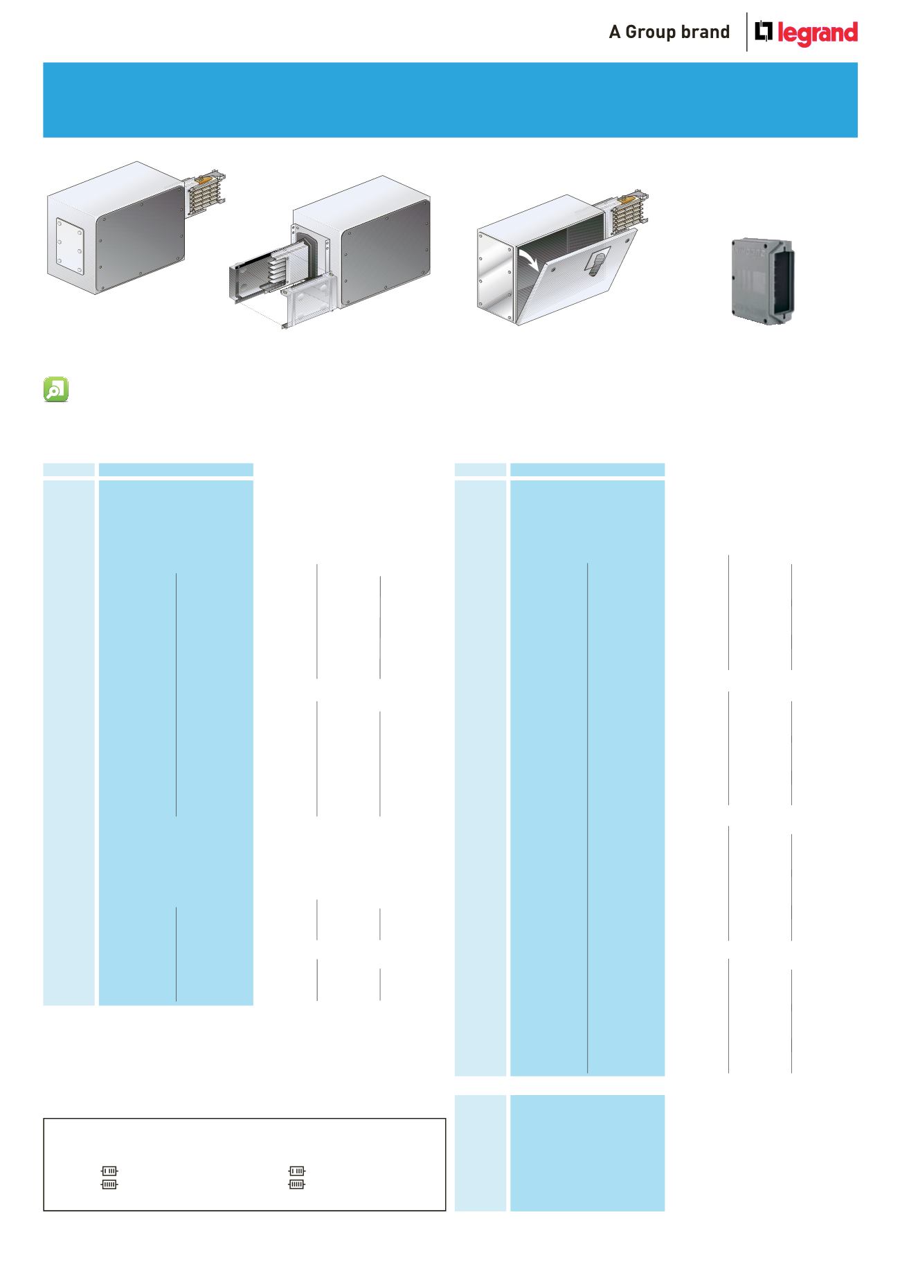
Feed unit
left end
Right end up feed
unit with AC23 switch
disconnector
End stop
Feed unit
right end
Key : How to select the correct configuration and finish
All examples on this page show 4 conductor galvanised lengths
No. of conductors and finish is dictated by the
red
number
0
= 4 conductors. Galvanised
2
= 4 conductors. Painted
1
= 5 conductors. Galvanised
3
= 5 conductors. Painted
Replace
0
with
1
,
2
, or
3
if required
4
5
- - -
0
- - - -
- - -
1
- - - -
- - -
2
- - - -
- - -
3
- - - -
Codes table
Conductors Case
Code
Painted
Painted
Galvanized
Galvanized
MR
MRF
MR-P
MRF-P
-
-
t l
t
i t
i t d
l
i
l
i
4
5
- - -
0
- - - -
- - -
1
- - - -
- - -
2
- - - -
- - -
3
- - - -
Codes table
Conductors Case
Code
Painted
Painted
Gal nized
Galvanized
MR
MRF
MR-P
MRF-P
-
-
-
t l
n t r
P i t
i t
l
i
G l
i
-
-
Dimensions and technical information p. 45 Measuring bespoke dimensions p. 49


