
111
Fig. 1
Fig. 2
Fig. 3
270 mm
Fig. 5
Fig. 6
Fig. 4
85Nm
n
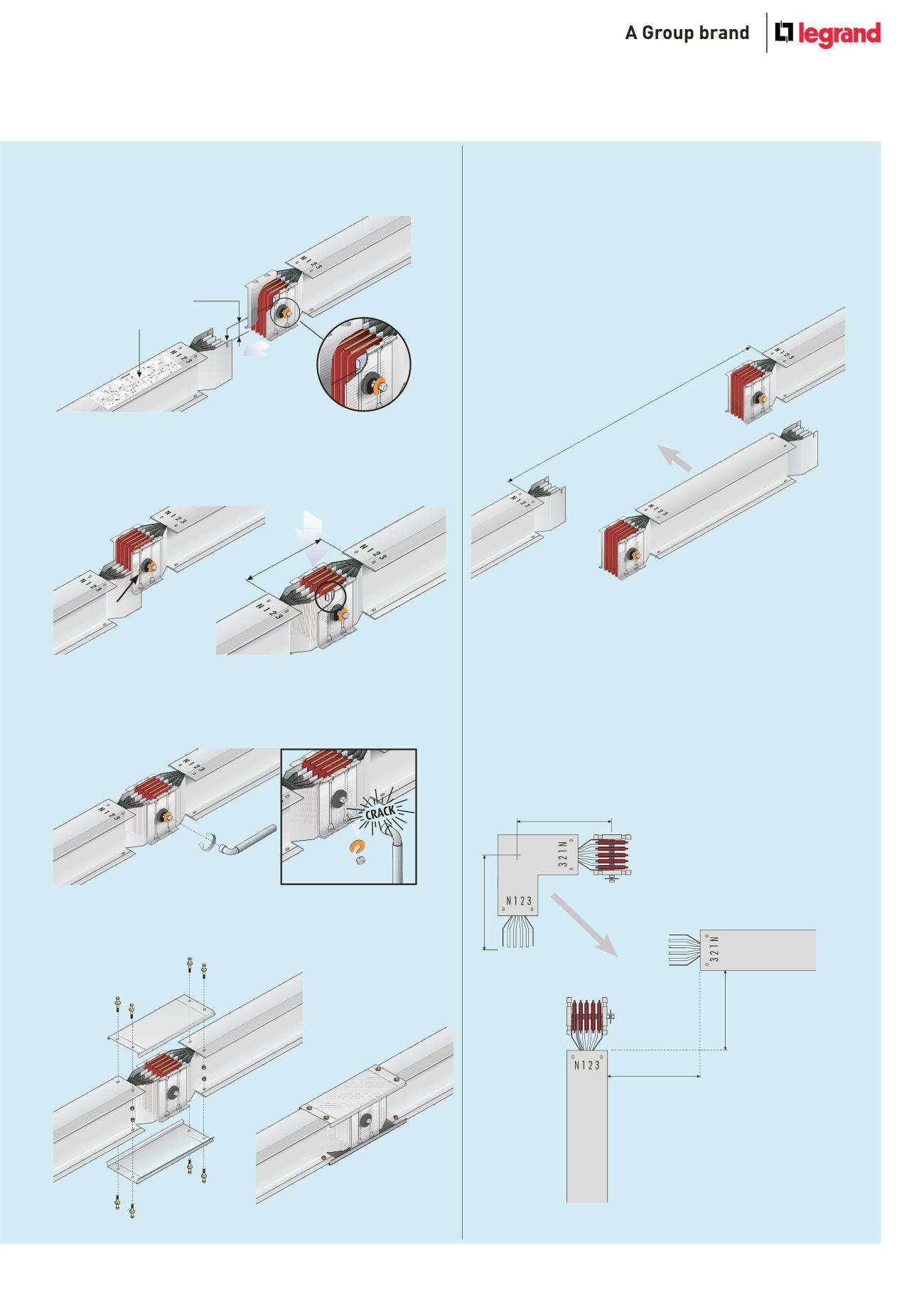
Installation sequence of the junction
Installation instructions are included near the junction (Fig.1)
Make sure that the contacts are clean before joining lengths
Install the junction covers (Fig. 5)
Completed IP 55 installation (Fig. 6)
For further information, please contact us on +44 (0) 845 600 6266
Tighten the bolt of the monobloc until the 1st head breaks off
(Fig. 4)
The bolt that tightens the monobloc has a second head which is
used when carrying out operations or inspections on the line
The nominal tightening torque is 85Nm
Make sure that the earth plate of the trunking length is inserted
behind the front plate of the junction monobloc (Fig.2)
The positioning pin on the monobloc should be fitted into the
corresponding slot on the earth plate. Verify the distance between
lengths, 270 mm, before tightening the monobloc completely (Fig.3)
30 mm
Measurement of trunking lengths
The exact length to be ordered can be determined by measuring
the distance between the components (as shown below) and then
subtracting 270 mm
Length = Q - 270 mm
Example : dimension measured = 2500 mm
length required = 2 230 mm
n
Measurement of bespoke components
N1 2 3
N1 2 3
N1 2 3
dimension Q
Q2
Q1
B = Q2 - 70 mm
A = Q1 - 70 mm
Horizontal elbow
The exact length to be ordered can be determined by measuring the
dimensions Q1 and Q2 (as shown below) and then subtracting 70 mm
from each dimension
A = Q1 - 70 mm
B = Q2 - 70 mm
For further information, please contact us on +44 (0) 845 600 6266
Instructions
All dimensions (mm) are nominal
1
2
3
4


