


 165 / 430

4.43
Sales Service Centre • 01952 675612 Technical Support Helpline • 01952 675689
Circuit Breaker Auxiliaries
Functions
Tripping and indication auxiliary contacts are common to the range of
multi-pole 10kA MCBs, and RCCBs. They should be mounted on the
left hand side of the device.
Auxiliary Contact MZ201 (Fig 9)
Allows remote indication of the status of the device contacts to which
it is associated.
Auxiliary Contact and Alarm Contact MZ202
This accessory has two separate functions. Like the MZ201 auxil-
iary contact, however the alarm contact will provide indication if the
breaker trips under fault conditions.
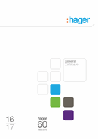
Wiring Diagram
MZ201 Auxiliary Contact and Alarm Contract
MZ203 Shunt Trip*
Allows tripping of the device by feeding the coil. The contacts also
allow for remote indication of operation.
MZ206 Under Voltage Release* (Fig 10)
Allows the MCB to trip when the voltage drops or by pressing a
remote off switch (i.e. emergency stop).
* Indication that the product has tripped due to the voltage release is
provided by a flag on the product.
MZ206 Under Voltage Release
Electrical Characteristics
MZ201/MZ206 MZ203
MZ206
1 x O 1 x C
Contact
230V ~ 6A
AC-1
230 - 415~
110 - 130...
230V~
50Hz
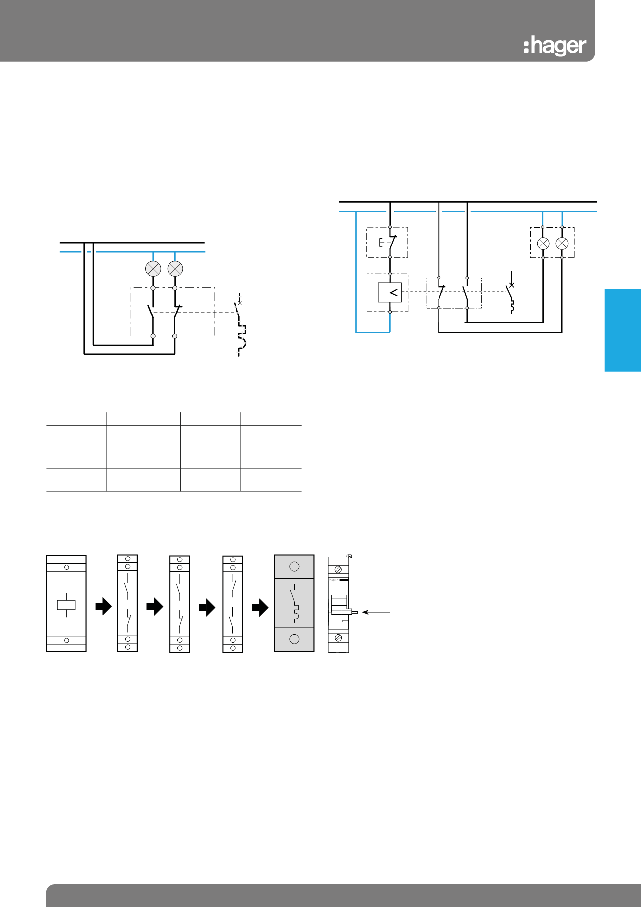
Grouping / Combination of Several Auxiliaries
On 2, 3 and 4 pole MCBs it is possible to associate 3 auxiliaries –
2 indication auxiliaries and 1 release auxiliary. In this case, it is important to first fix the indication auxiliary (MZ201 and MZ202) and then the
release auxiliary (MZ203 and MZ206).
Electrical connection
By terminal fitted with fixed clamp screws wiring capacity.
Flexible : 2 x 1.5mm2
Rigid : 2 x 1.5mm2
MZ203
Power - 8VA
tolerance : -15% of U n
MZ206
Latching voltage is between 35 and 70% of U n 230V~
Coil consumption 3VA
Flag indicating that the
product has tripped due to
the voltage release
MZ203 to MZ206
Fig. 12
MZ203 to
MZ206
Fig. 11
MZ201 to
MZ201
+
+
+
+
MZ201 to
MZ201
MZ202 to
MZ201
MCB
MZ206
D1
D2
MZ202
U
91
92
93
94
Ph
N
Fig. 10
Fig. 9
22
21
14
13
MZ 201
Ph
N
Protection
Devices