


 160 / 430

4.38
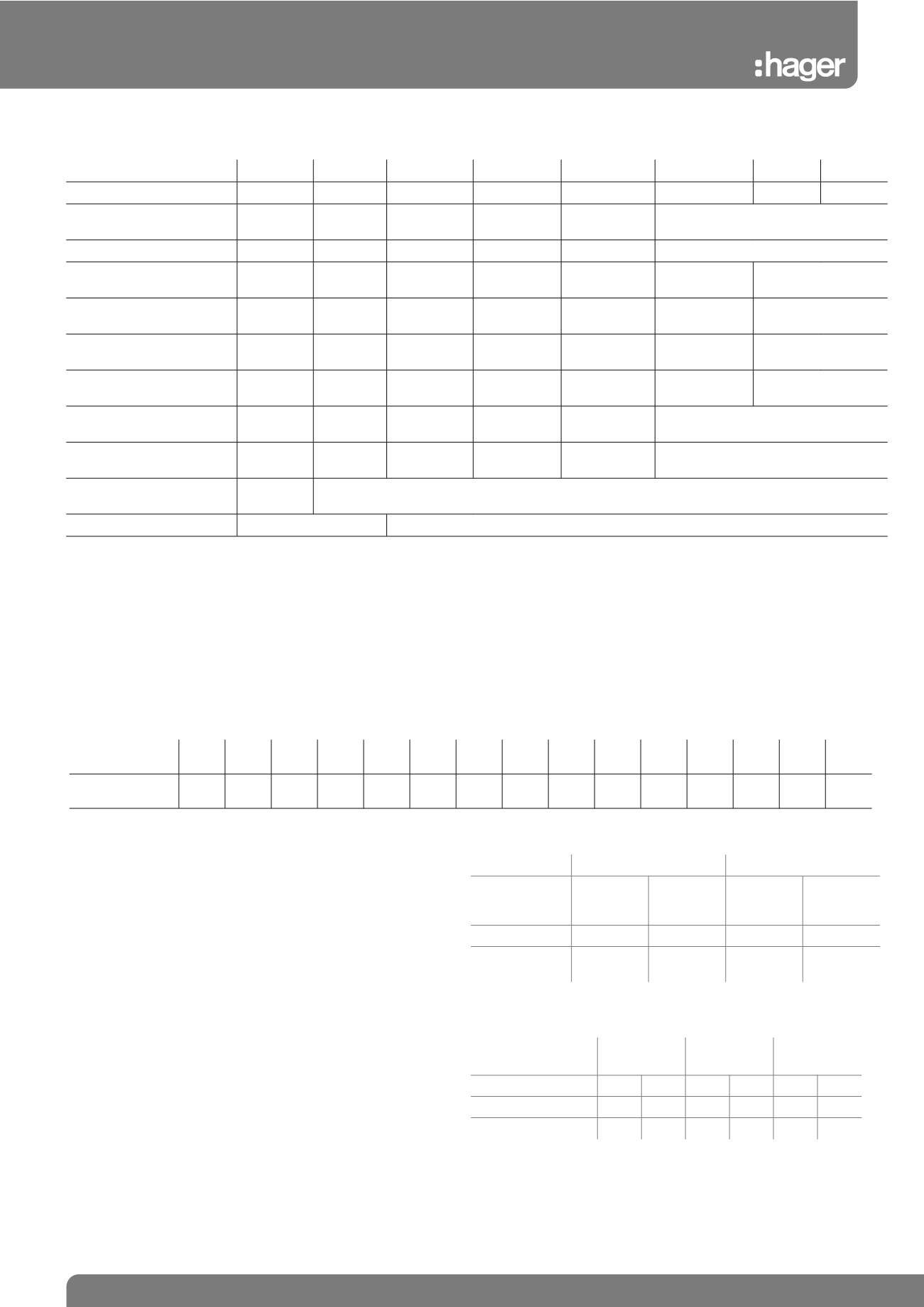
General Catalogue • Protection Devices • Technical
Miniature Circuit Breakers
Electrical Characteristics
MLN
MTN
NBN
NCN
NDN
HMF*
HMC*
HMD*
Poles
SP+SN SP
SP DP TP 4P SP DP TP 4P SP DP TP 4P SP DP TP 4P
Rated Operational Voltage
Ue (V)
230
230
230 / 400 230 / 400
230 / 400
230/400
Nominal Current
6 - 40A 6 - 63A 6 - 63A
0.5 - 63A 0.5 - 63A
80 - 125A
Breaking Capacity (Icn)
to BS EN 60898
6kA
6kA
10kA
10kA
10kA
10kA
15kA
Breaking Capacity (Ics)
to BS EN 60898
6kA
6kA
7.5kA
7.5kA
7.5kA
7.5kA
7.5kA
Breaking Capacity (Icu)
to BS EN 60947 Part 2
N/A
N/A
15kA
15kA
15kA
N/A
15kA
Breaking Capacity (Ics)
to BS EN 60947 Part 2
N/A
N/A
7.5kA
7.5kA
7.5kA
N/A
7.5kA
Rated Insulation Voltage
Ul (V)
500V
500V
500V
500V
500V
500V
Rated Impulse Voltage
Uimp (kV)
4kV
4kV
6kV
6kV
6kV
6kV
Electrical Endurace
10,000
cycles
10,000 cycles
Connection of Auxiliaries
No
Yes
*Din rail mount only, not for use in fixed busbar distribution boards.
Power Loss
The power loss of MCB’s is closely controlled by the standards and is calculated on the basis of the voltage drop across the main
terminals measured at rated current. The power loss of hager circuit breakers is very much lower than that required by the British Standard, so
in consequences run cooler and are less affected when mounted together.
The table below gives the watts loss per pole at rated current.
MCB Rated
current (A)
0.5 1
2
3
4
6
10 13 16 20 25 32 40 50 63
Watts loss per
pole
1.2 1.3 1.5 2.0 1.8 1.4 1.9 2.1 2.5 2.8 3.2 3.8 4.0 4.5 5.1
Table 1
For use with DC
Because of their quick make and break design and excellent arc
quenching capabilities, Hager circuit breakers are suitable for DC
applications.
The following parameters must be considered:
1. System voltage:
Determined by the number of poles connected in series (see table 14)
2. Short circuit current:
(See table 14)
3. Tripping Characteristics:
The thermal trip remains unchanged
the magnetic trip will become less sensitive requiring derating by √2
the ac value (See table 14)
No. of poles 1 pole
2 poles in series
Range
max
voltage
breaking
capacity
L/R=15ms
Max
voltage
breaking
capacity
L/R=15ms
MTN
60V
6kA
125V
6kA
NCB NCN
NDN
60V
10kA
125V
10kA
Table 13
Characteristic
curve
B
C
D
Magnetic strip
50Hz dc 50Hz dc 50Hz dc
Irm1
3In 4.5 In 5In 7.5 In 10 In 15 In
Irm2
5In 7.5 In 10In 15 In 20 In 30 In
Table 14