


 161 / 430

4.39
Sales Service Centre • 01952 675612 Technical Support Helpline • 01952 675689
Miniature Circuit Breakers
Connection
The circuit breaker can have the line\load connected to either the top or bottom terminals
Temperature Derating
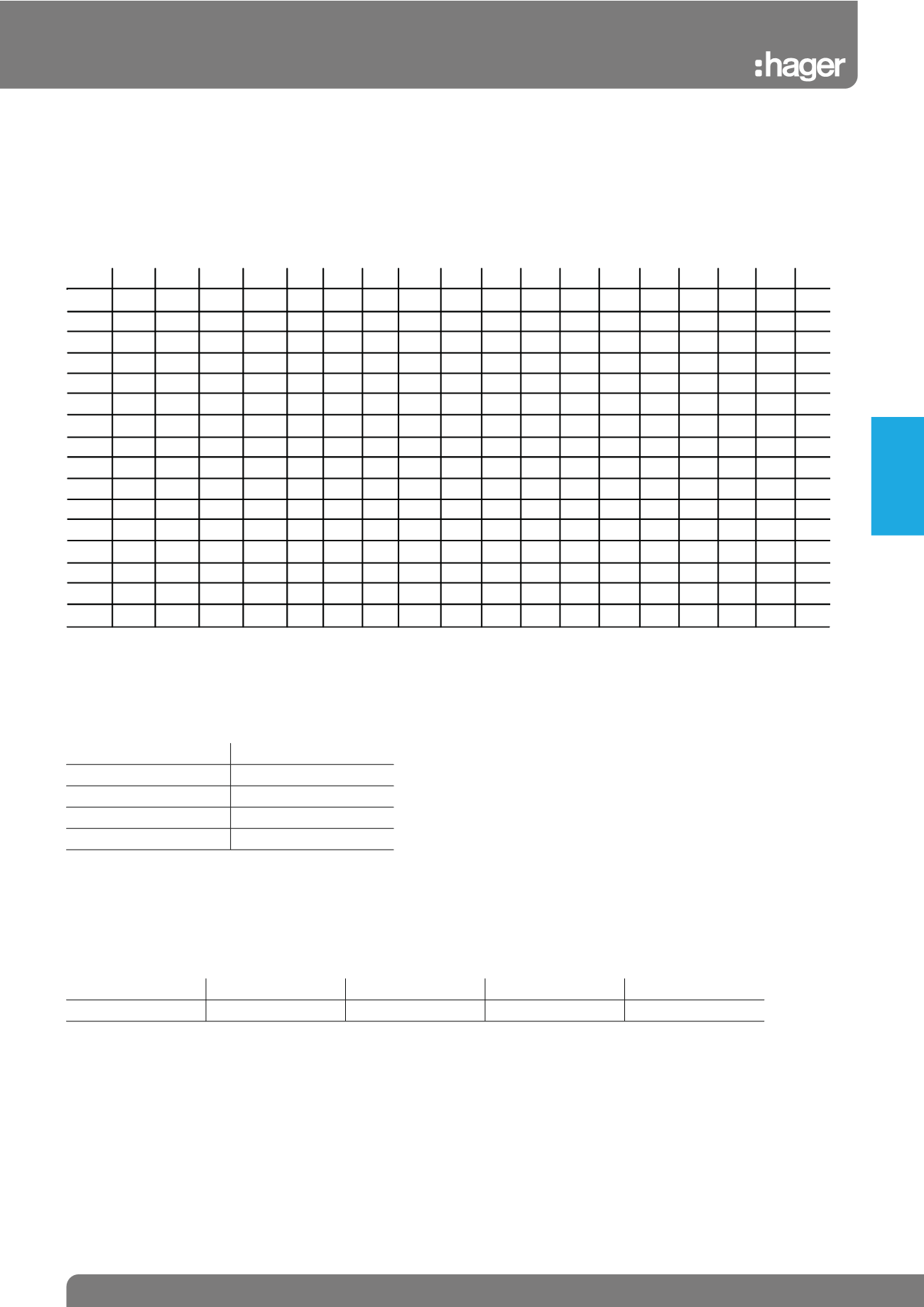
MCBs are designed and calibrated to carry their rated current and to operate within their designated thermal time/current zone at 30ºC. Testing
is carried out with the breaker mounted singly in a vertical plane in a controlled environment. Therefore if the circuit breaker is required to
operate in conditions which differ from the reference conditions, certain factors have to be applied to the standard data.
In (A) -25°C -20°C -15°C -10°C -5°C 0°C 5°C 10°C 15°C 20°C 25°C 30°C 35°C 40°C 45°C 50°C 55°C 60°C
0.5
0.72 0.7 0.68 0.66 0.64 0.62 0.6 0.58 0.56 0.54 0.52 0.5 0.48 0.46 0.44 0.42 -
-
1
1.44 1.4 1.36 1.32 1.28 1.24 1.2 1.16 1.12 1.08 1.04 1 0.96 0.92 0.88 0.84 0.8 0.76
2
2.88 2.8 2.72 2.64 2.56 2.48 2.4 2.32 2.24 2.16 2.08 2 1.92 1.84 1.76 1.68 1.6 1.52
3
4.32 4.2 4.08 3.96 3.84 3.72 3.6 3.48 3.36 3.24 3.12 3 2.88 2.76 2.64 2.52 2.4 2.28
4
5.76 5.6 5.44 5.28 5.12 4.96 4.8 4.64 4.48 4.32 4.16 4 3.84 3.68 3.52 3.36 3.2 3.04
6
8.64 8.4 8.16 7.92 7.68 7.44 7.2 6.96 6.72 6.48 6.24 6 5.76 5.52 5.28 5.04 4.8 4.56
10
14.4 14 13.6 13.2 12.8 12.4 12 11.6 11.2 10.8 10.4 10 9.6 9.2 8.8 8.4 8 7.6
13
18.7 18.2 17.7 17.2 16.6 16.1 15.6 15.1 14.6 14.0 13.5 13 12.5 12.0 11.4 10.9 10.4 9.9
15
21.6 21 20.4 19.8 19.2 18.6 18 17.4 16.8 16.2 15.6 15 14.4 13.8 13.2 12.6 12 11.4
16
23.0 22.4 21.8 21.1 20.5 19.8 19.2 18.6 17.9 17.3 16.6 16 15.4 14.7 14.1 13.4 12.8 12.2
20
28.8 28 27.2 26.4 25.6 24.8 24 23.2 22.4 21.6 20.8 20 19.2 18.4 17.6 16.8 16 15.2
25
36 35 34 33 32 31 30 29 28 27 26 25 24 23 22 21 20 19
32
46.1 44.8 43.5 42.2 41.0 39.7 38.4 37.1 35.8 34.6 33.3 32 30.7 29.4 28.2 26.9 25.6 24.3
40
57.6 56 54.4 52.8 51.2 49.6 48 46.4 44.8 43.2 41.6 40 38.4 36.8 35.2 33.6 32 30.4
50
-
-
-
-
-
62 60 58 56 54 52 50 48 46 44 42 40 38
63
-
-
-
-
-
-
-
-
-
-
-
63 60.5 58.0 55.4 52.9 50.4 47.9
Diversity Factor
Consideration should be given to the proximity heating effect of the breakers when fully loaded and mounted together in
groups.
Adjacent circuit breakers having a load 'on' time exceeding 30 minutes or where the load not exceeding 30 minutes has
an 'off' time less than the 'on' time, will need to have the rated diversity factor applied.
No. of Outgoing Circuits Assumed Loading Factor
2 and 3
0.8
4 and 5
0.7
6 to 9 inclusive
0.6
10 and above
0.5
Frequency
Circuit breakers are designed to operate at a frequency of 50-60Hz. Should the supply differ from this then the following fac-
tors should be applied
Thermal – unchanged
Magnetic – value multiplied by coefficient K
F (Hz)
17Hz - 60Hz
100Hz
200Hz
400Hz
K
1
1.1
1.2
1.5
Consideration should be given to the proximity heating effect of the breakers when fully loaded and mounted together in
groups. (continuously & simultaneously loaded).
Protection
Devices