
Data is subject to errors and technical modifications.
1.39
Surge Protection
Surge Protection
Surge Protection
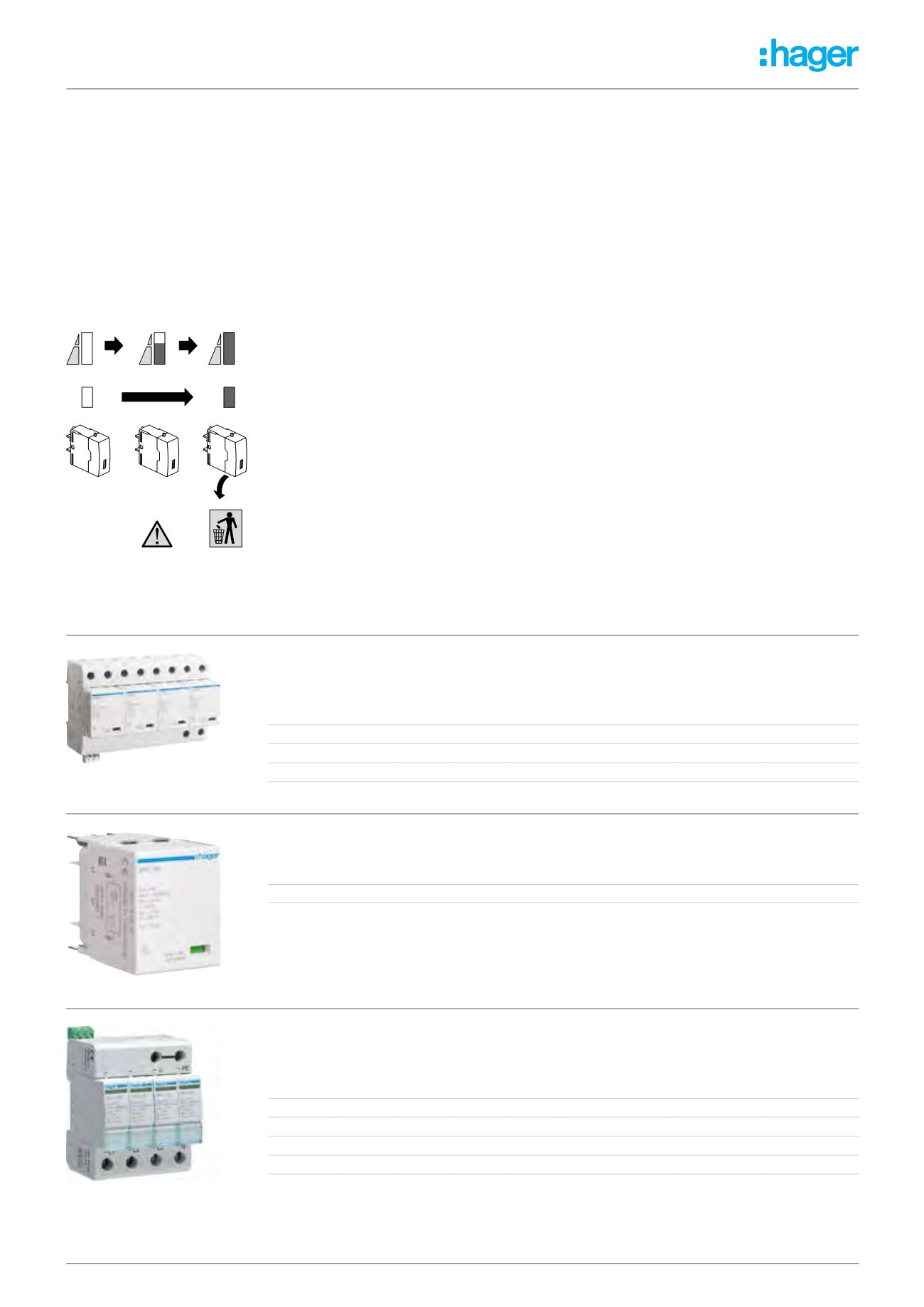
Class 1 + 2 (Class 1 + 2 + 3 if less than 5m) (with lifetime indicator)
Class 2 (with lifetime indicator)
Replacement Cartridges (SPN8* Range)
Characteristics
-
-
SPD’s protect electrical and electronic equipment against transients, originating from lightning, switching of transformers,
lighting and motors. These transient voltages can cause premature ageing of equipment, downtime, or complete destruction
of electronic components and materials. SPDs are strongly recommended on installations that are exposed to transient
voltages, to protect sensitive and expensive electrical equipment such as TV, video, Hi-Fi, PC, alarm etc.
-
-
The range of SPDs is separated into three types of protection:
1. Main protection - class 1
SPDs with higher discharge current (I max 10/350), to evacuate as much of the transient over-voltages associated with
lightening strikes
2. Main protection - class 2
With a discharge current (I max 8/20), to evacuate as much of the transient over-voltage to earth as possible protection
level (Up ≤ 1200V).
3. Main protection - class 3
To cut-down the transient surge as low as possible to protect very sensitive equipment.
Technical Data
-
-
Conforms to IEC61643-1.
-
-
R Versions: reserve status indicator, signalling.
-
-
D Versions: end of life indicator, auxiliary contact for remote indication.
-
-
Connection Capacity (terminal blocks L, N & E): Rigid conductor: 10mm², Flexible conductor: 6mm².
-
-
230V a.c. 1A.
-
-
12V...10mA.
Installation and Connection
-
-
The main protection SPDs are installed directly after the main incoming switch or RCCB
-
-
SPDs are suitable for any supply system e.g TNCS, TNS, TT.
-
-
Connected in parallel to the equipment to be protected.
-
-
Protection is assured in both common and differential modes.
SPDs with Low Let Through Voltage Levels Type 3
-
-
To protect very sensitive electronic equipment. This fine protection complements the main protection and can protect one or
many electronic devices.
-
-
Optimal coordination is obtained when cascaded with a main protection device.
-
-
A green LED on the front face indicates the status of the
SP202N
, connected in series with the equipment that needs to be
protected (with a maximum line current of 25A). Protection is assured in both common and differential modes.
Replacement Cartridges
-
-
Allow simple replacement without the need to cut-off the power supply.
-
-
Cartridges are available for all discharge currents (40kA and 15kA) with and without condition indication.
-
-
A keying system exists to prevent a line cartridge being interchanged by mistake with a neutral one and visa versa. Neutral
cartridges have a discharge current of 65kA.
-
-
For technical details see page
1.89AI1_SP115P_T1_02
OK
AI1_SP115P_T1_02
OK
Poles
I imp
L-N
I imp
N-PE
U p kV
Single or
Three
Phase
Width (mm)
Cat ref.
Cat ref.
with remote
contact
2
12.5
25
≤1.5
Single 35
SPA201
-
4
12.5
50
≤1.5
Three
70
SPA401
-
4
25
100
≤1.5
Three
140
SPN801
SPN801R
4
25
100
≤1.5
Three
140
SPN802
SPN802R
Poles
I n kA
L-N
I n kA
N-PE
U p kV
Single or
Three
Phase
Width (mm)
Cat ref.
Cat ref.
with remote
contact
1
5
15
≤ 1.2
Single 17.5
SPN115D
SPN115R
2
5
15
≤ 1.2
Single 35
SPN215D
SPN215R
2
15
40
≤ 1.2
Single 35
SPN240D
SPN240R
4
5
15
≤ 1.5
Three
70
SPN415D
SPN415R
4
15
40
≤ 1.5
Three
70
SPN440D
SPN440R
Description
Cat ref.
Phase replacement for
SPN801
,
SPN801R
,
SPN802
,
SPN802R
SPN080
Neutral replacement for
SPN801
,
SPN801R
,
SPN802
,
SPN802R
SPN080N
SPN801R
SPN080
SPN415D
Commercial
Distribution


