


 359 / 582

BETA Switching
Switching Devices
5
TT4 2 switching relays
8/11
Siemens ET B1 · 10/2008
8
*
You can order this quantity or a multiple thereof.
■
Overview
Switching relays are used in residential, non-residential and
industrial buildings for the purpose of contact multiplication.
They can be used with safe isolation between coil voltage and
contact. Switching relays for direct voltages in particular find
increasing use.
With the 5TE9 100 and 5TE9 101 busbar, the switching relays
can be mounted quickly and safely, e.g. by bus-mounting the
N-conductor and/or infeed
–
and this applies to the whole range
of switching relays.
■
Benefits
•
Fast and simple installation thanks to bus-mounting
•
Switching position indicator when checking the plant for
enhanced safety
•
Manual intervention possible at any time – easy fault locating
due to manual operation.
■
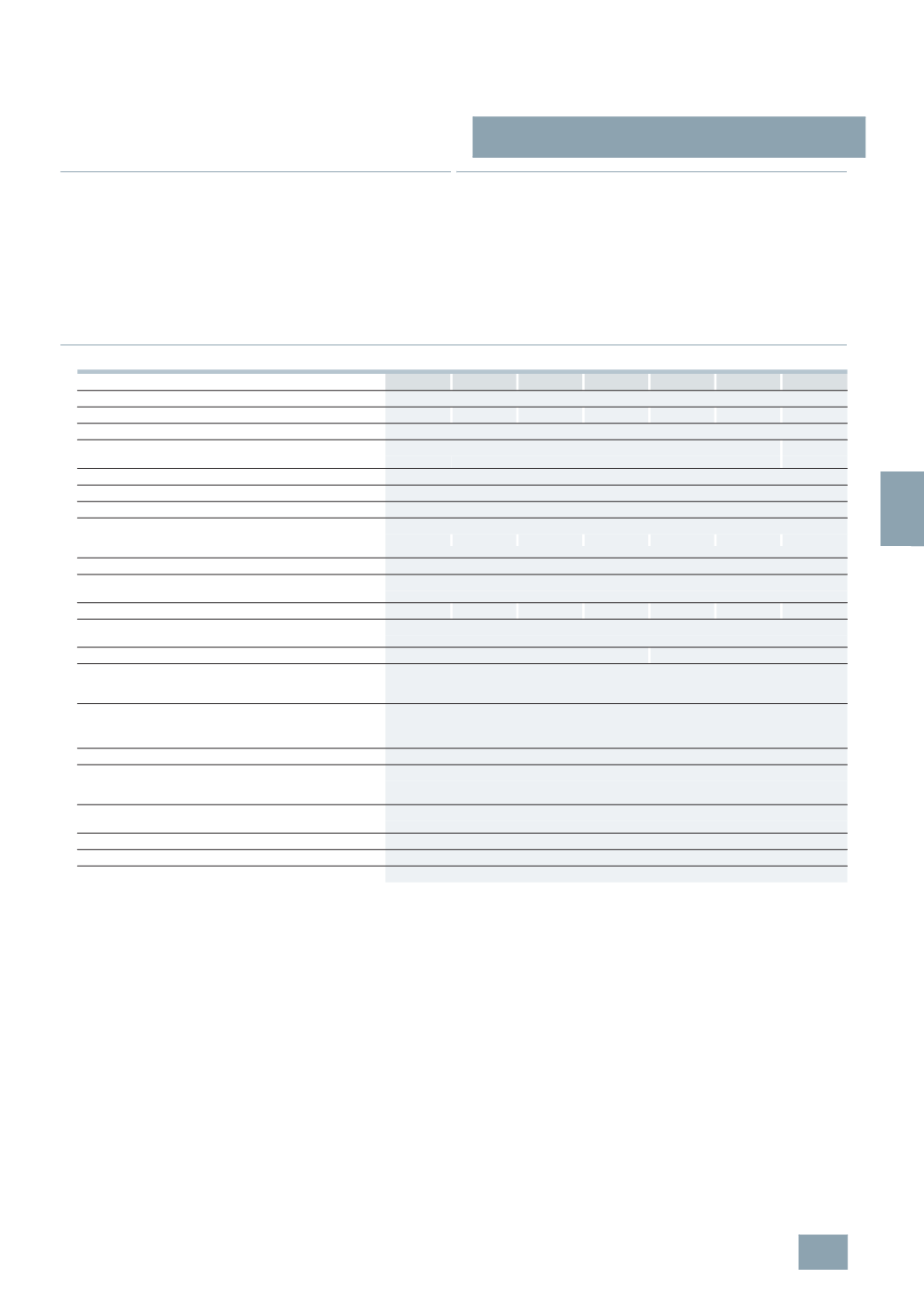
Technical specifications
5
TT4 201-. 5TT4 202-. 5TT4 204-. 5TT4 205-. 5TT4 206-. 5TT4 207-. 5TT4 217-.
Standards
EN 60947-5-1, EN 60669-2-2
Contact type
1
NO 2 NO 4 NO 1 NO 1 NC 1 CO 2 CO 2 CO
Manual operation
Yes
Rated control voltage U
c
V AC 8 ... 230
--
V DC --
12 ... 110
Operating range
× U
c
0.8 ... 1.1
Rated frequency f
c
Hz
50
Rated impulse withstand voltage U
imp
kV
4
Rated power dissipation P
v
•
Magnet coil
W/VA 2.4/3.0
2.4/3.0
4.8/6.0
2.4/3.0
2.4/3.0
2.4/3.0
1.7
•
Per contact at 16 A
W 1.0
Minimum contact load
V AC; mA 10; 100
Rated operational current
I
e
At p.f. = 0.6 ... 1
A
16
Rated operational voltage U
e
250
400
400
400
250
400
400
Different phases
Between magnet coil/contact
Permissible
Contact gap
mm > 1.2
< 1.2
Safe isolation
Between creepage distances and clearances
magnet coil/contact
mm > 6
Electrical service life
At
I
e
/
U
e
or specified lamp load
Operating
cycles
50000
Terminals
± screw (Pozidriv)
1
Conductor cross-sections
•
Rigid
mm
2
1.5 ... 6
•
Flexible, with end sleeve
mm
2
1 ... 6
Resistance to climate
At 95 % relative humidity Acc. to DIN 50015 °C
35
Permissible ambient temperature
°C
-10 ...
+40
Degree of protection
Acc. to EN 60529
IP20, with connected conductors
Mounting position
Any
© Siemens AG 2008