


 355 / 582

BETA Switching
Switching Devices
5
TT4 1 remote control switches
8/7
Siemens ET B1 · 10/2008
8
*
You can order this quantity or a multiple thereof.
Remote control switches with central and group ON/OFF switching
Auxiliary switches
Compensators
■
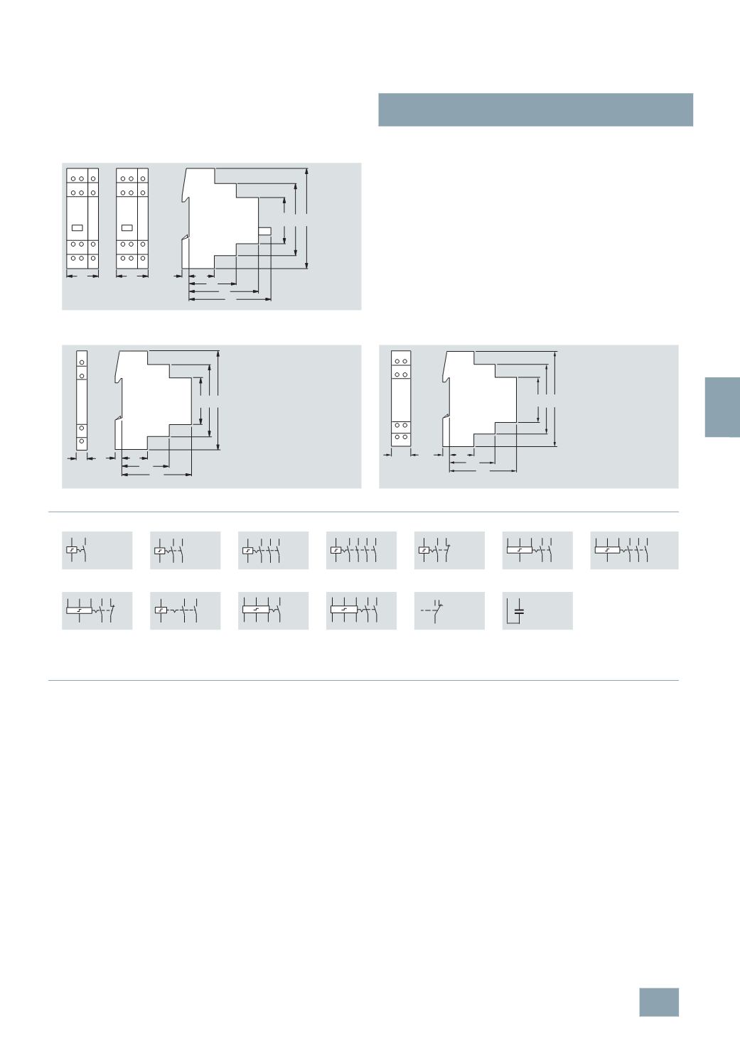
Schematics
■
More information
Mechanical storage
Remote control switches are used to switch lighting by means of
several pushbuttons. This makes complex cross/two-way
switching unnecessary. With each pushbutton impulse, the
remote control switch changes its contact position from OFF
to ON, etc. In the event of a power failure, the last switching
position is mechanically stored. Electromechanical remote
control switches have no standby loss.
Pushbutton malfunction
Pushbuttons can jam, which may expose remote control switches
to a continuous voltage. All remote control switches are protected
against this type of malfunction through their design or through
PTC.
Central switching functions
Versions with central ON/OFF functions allow the central switching
of all connected remote control switches, which can also be carried
out over a clock timer.
All remote control switches can be switched to the ON or OFF
switching state, regardless of their current switching state.
Contact sequences
0 – 1 – 2 – 1
+2
or
1 – 0 – 2 – 0
means:
0:
No contact closed
1:
Only contact 1 closed
2:
Only contact 2 closed
1
+2: Contact 1 and contact 2 are closed
The contact positions are constantly changing with each
pushbutton impulse.
5
TT4 151 5TT4 152
A1
ZE
ZA
N GAGE
1
2
1
2
3
4
A1
ZE
ZA
N GAGE
44
64
70
45
67
90
7 24
27
27
I2_13757
5
TT4 90.
5
TT4 920
5
TT4 101
5
TT4 102
5
TT4 103
5
TT4 104
5
TT4 105
5
TT4 115
5
TT4 122-0
5
TT4 123-0
5
TT4 125-0
5
TT4 132
5
TT4 142
5
TT4 151
5
TT4 152
5
TT4 90.
5
TT4 920
I2_13708
45
90
44
7
67
24
64
A1
18
A2
A1 2
1
A2
A1 2 4
1 3
A2
A1 2 4 6
1 3 5
A2
A1
A2
2
1
4
3
6
5
8
7
A2 1
A1 2
3
4
A1 ZE ZA
N
1
2
3
4
A1 ZEZA
N
1
2
3
4
5
6
A1 ZE ZA
N
1
2
3
4
A1
N
11
12 24
23
ZA ZE A1 1
GAGEN 2
ZA ZE A1 1
GAGEN 2
3
4
11
12
14
A1 A2
© Siemens AG 2008