


 357 / 582

BETA Switching
Switching Devices
5
TT4 1 remote control switches
8/9
Siemens ET B1 · 10/2008
8
*
You can order this quantity or a multiple thereof.
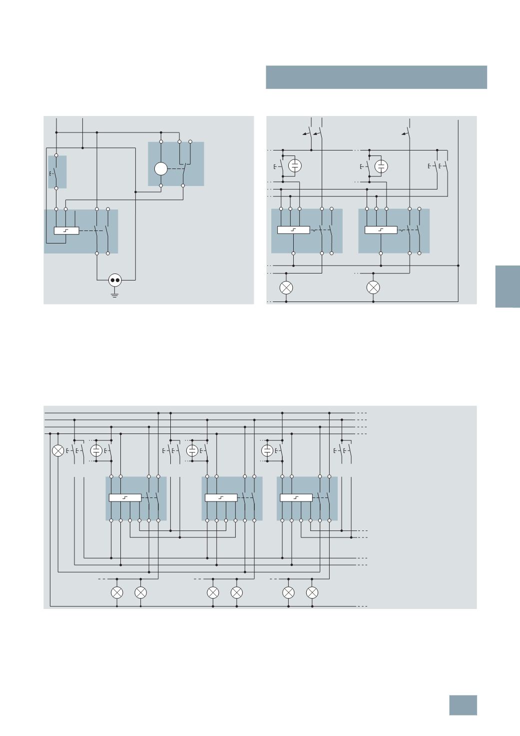
Switching example: 5TT4 122-0
with central ON/OFF switching and time switch
Printers and copiers are to be switched on with the pushbutton
at the beginning of the working day. At the end of the working
day, e.g. 6 p.m. to 10 p.m., an hourly one-second pulse of the
time switch switches off the socket outlet. This ensures that
printers and copiers are not "forgotten". If the device is switched
on again after 6 p.m., a switch-off is actuated again hourly.
Switching example: 5TT4 122-0
with central ON/OFF switching
With the pushbuttons for ON/OFF switching, all remote control
switches can be switched on or off from a central point, e.g. at
the start and end of work. A time switch with a one-second pulse
(
e.g. 7LF4 444-0) can also be used if desired. Once a central
on/off switching operation has been done, the remote control
switches can also be switched on and off locally at any time. The
phase relation of ZA, ZE and A1 is arbitrary. Remote control
switches with central ON/OFF switching can also be used to
quickly and easily set up a panic circuit/panic lighting using
conventional installation methods.
Switching example: 5TT4 152-0 with central ON/OFF switching and group ON/OFF switching
With the pushbuttons for ON/OFF switching, all remote control
switches can be switched on or off from a central point, e.g. at
the start and end of work.
With the 2-pushbutton group "ON" and "OFF" function, all remote
control switches assigned to a group can be switched on or off,
e.g. corridor. A 7LF44 digital time switch with a switching command
of 1 s can also be used for the "Central" or "Group" function.
Once a central on/off switching operation has been done, the re-
mote control switches can also be switched on and off locally at
any time. The phase relations of ZA, ZE and GA, GE and L may
vary. If contact 1/2 is used as check-back contact for the central
"
ON" and "OFF" function, as shown above, terminal 1 of all re-
mote control switches must be in phase.
~
I2_13694a
5
ZA ZE A1
L1
N
N
M
3
4
1
2
1
2
5
TT4 122-0
5
TE6 800
7
LF4 411-0
5
TE4 800
2
1
4
3
230
V AC
N
L2
L3
N
L1
N
2 4
1 3
2 4
1 3
ZE A1
ZA
ZE A1
ZA
Central
On/Off
3
x 230 V AC
I2_12180b
L1
N
L2
L3
1
L
3
42
N
GA GE ZA ZE
1
L
3
42
N
GA GE ZA ZE
1
L
3
42
N
GA GE ZA ZE
I2_13695a
Group 2
ON/OFF
Group 1
ON/OFF
Central
ON/OFF
3
x 230 V AC
© Siemens AG 2008