


 364 / 582

BETA Switching
Switching Devices
5
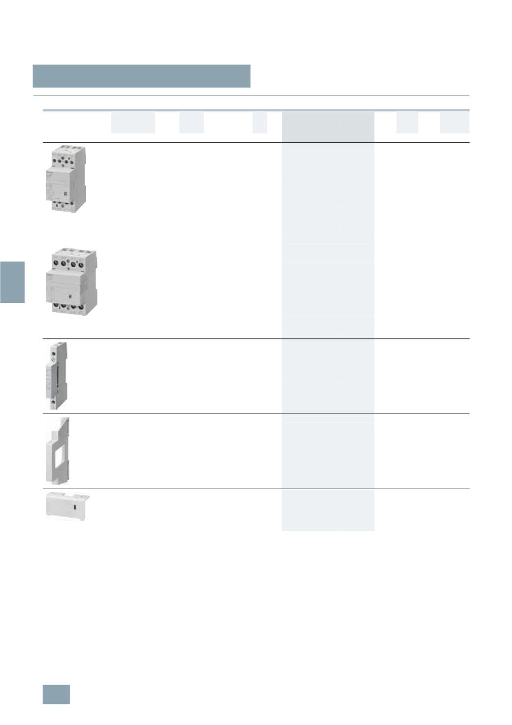
TT5 7 Insta contactors, DC technology
8/16
Siemens ET B1 · 10/2008
8
*
You can order this quantity or a multiple thereof.
■
Selection and ordering data
1)
For NC contacts 30 A.
Contacts
U
e
I
e
U
c
MW DT Order No.
Price
per PU
PG PU PS*/
P. unit
Weight
per PU
approx.
V AC A AC V AC V DC
Unit(s) Unit(s) kg
5
TT5 730-0
Insta contactors
For AC or DC continuous operation,
with switching position indication,
with DC magnetic system
4
NO
440 24
230 220 2
A
5
TT5 730-0
027 1
1
0.247
115 110
B
5
TT5 730-1
027 1
1
0.247
24
24
A
5
TT5 730-2
027 1
1
0.247
3
NO, 1 NC 440 24
230 220 2
A
5
TT5 731-0
027 1
1
0.247
24
24
A
5
TT5 731-2
027 1
1
0.247
2
NO, 2 NC 440 24
230 220 2
A
5
TT5 732-0
027 1
1
0.247
24
24
A
5
TT5 732-2
027 1
1
0.247
4
NC
440 24
230 220 2
A
5
TT5 733-0
027 1
1
0.247
24
24
B
5
TT5 733-2
027 1
1
0.247
5
TT5 740-0
4
NO
440 40
230 220 3
A
5
TT5 740-0
027 1
1
0.410
24
24
A
5
TT5 740-2
027 1
1
0.410
3
NO, 1 NC 440 40
1)
230 220 3
A
5
TT5 741-0
027 1
1
0.410
24
24
B
5
TT5 741-2
027 1
1
0.410
2
NO, 2 NC 440 40
1)
230 220 3
A
5
TT5 742-0
027 1
1
0.410
24
24
B
5
TT5 742-2
027 1
1
0.410
4
NO
440 63
230 220 3
A
5
TT5 750-0
027 1
1
0.410
24
24
A
5
TT5 750-2
027 1
1
0.410
3
NO, 1 NC 440 63
1)
230 220 3
B
5
TT5 751-0
027 1
1
0.410
24
24
B
5
TT5 751-2
027 1
1
0.410
2
NO, 2 NC 440 63
1)
230 220 3
B
5
TT5 752-0
027 1
1
0.410
24
24
B
5
TT5 752-2
027 1
1
0.410
Auxiliary switches
For left-sided mounting on the 24 A, 40 A and 63 A Insta
contactors, max. one auxiliary switch per Insta contactor,
minimum contact load 24 V AC; 5 mA
2
NO
230
AC-15
4
0.5
}
5
TT5 900
027 1
1
0.039
1
NO, 1 NC 230
AC-15
4
0.5
}
5
TT5 901
027 1
1
0.039
Spacers
For heat dissipation between the Insta contactors.
We recommend placing a spacer after every
second Insta contactor.
Can be mounted reciprocally, so that
two spacers enable greater cable penetration.
0.5
}
5
TG8 240
027 1
2
0.010
Sealable terminal covers
For Insta contactors 24 A,
(1
set = 2 units)
2
B
5
TT5 902
027 1
set
1
set
0.010
For Insta contactors 40 A and 63 A
(1
set = 2 units)
3
B
5
TT5 903
027 1
set
1
set
0.010
© Siemens AG 2008