


 348 / 582

BETA Switching
Switches and Light Indicators
5
TE1 switch disconnectors
7/28
Siemens ET B1 · 10/2008
7
*
You can order this quantity or a multiple thereof.
■
Schematics
5
TE1 switch disconnectors
5
STE9 auxiliary switches
■
More information
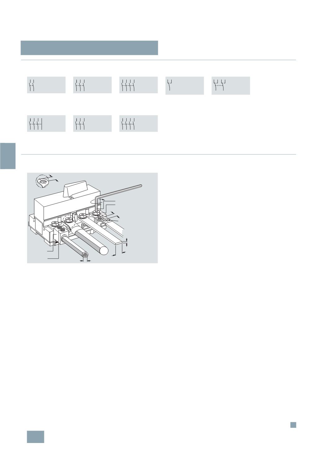
Connection of 5TE1 .3 and 5TE1 .4 switches, 160 A and 200 A Design
•
From 160 A: supplied with one terminal cover
• 160
A and 200 A: version for connection with cable lug
•
Screw fixing on base plate
•
Installation on standard mounting rail according to EN 60715,
which is raised at least 5 mm from the base plate
5
TE1 210
5
TE1 220
5
TE1 230
5
TE1 240
5
TE1 310
5
TE1 320
5
TE1 330
5
TE1 340
5
TE1 410
5
TE1 420
5
TE1 430
5
TE1 440
5
TE1 610
5
TE1 620
5
TE1 630
5
TE1 640
5
TE1 315
5
TE1 325
5
TE1 335
5
TE1 345
5
TE1 415
5
TE1 425
5
TE1 435
5
TE1 445
5
TE9 005
5
TE9 006
10-12
max. 12 Nm
SW 5
SW 13
10-12
max. 6
20
max.
SW 5
5
TE9 003
5
TE9 004
I2_08070a
max. Ø14
Ø8,5
© Siemens AG 2008