


 347 / 582

BETA Switching
Switches and Light Indicators
5
TE1 switch disconnectors
7/27
Siemens ET B1 · 10/2008
7
*
You can order this quantity or a multiple thereof.
■
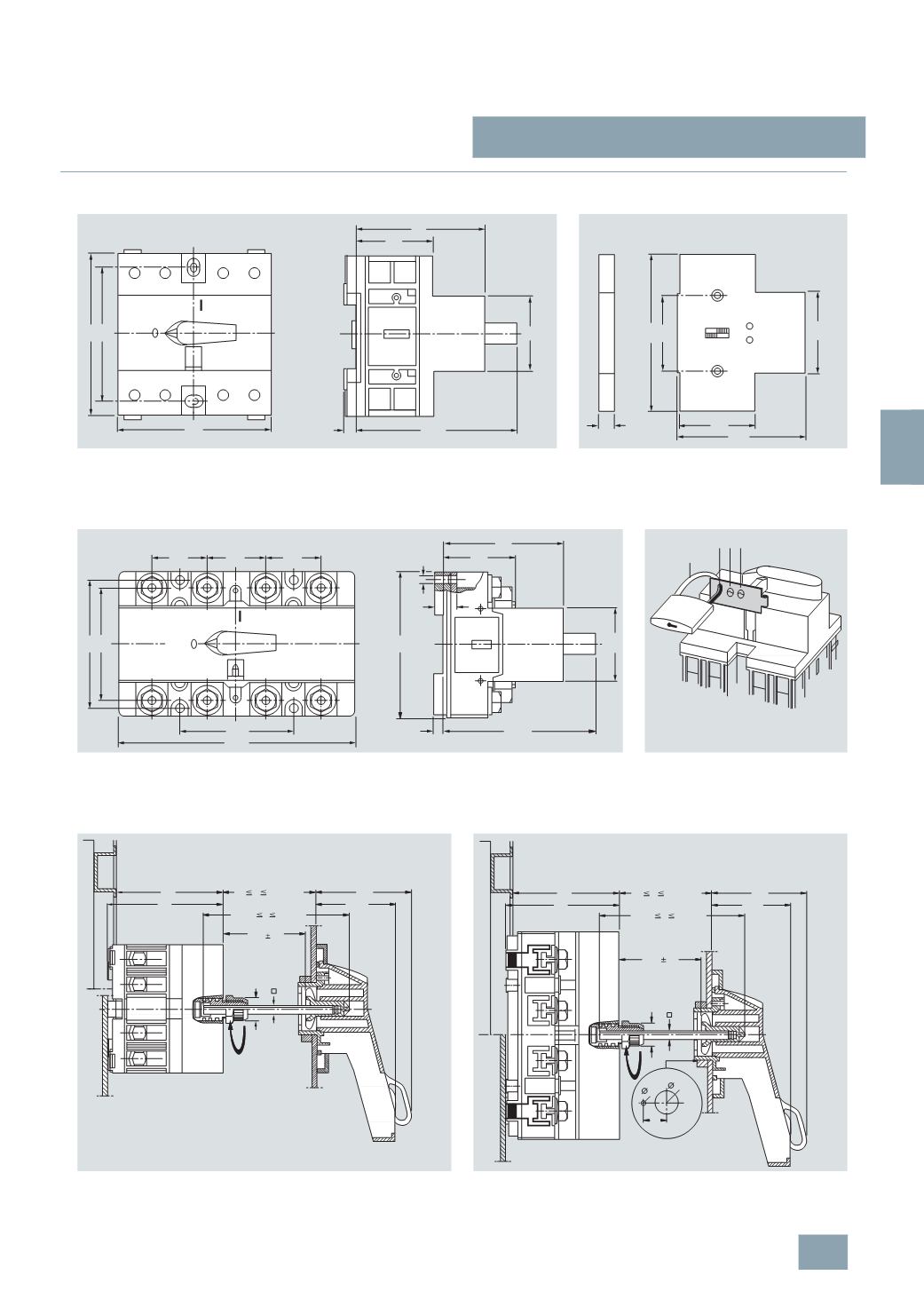
Dimensional drawings
5
TE1 switch disconnectors, 100 A and 125 A
5
TE9 auxiliary switches
5
TE1 210
5
TE1 220
5
TE1 310
5
TE1 320
5
TE1 315
5
TE1 325
5
TE1 410
5
TE1 420
5
TE1 415
5
TE1 425
5
TE1 610
5
TE1 620
5
TE9 005
5
TE9 006
5
TE1 switch disconnectors
5
TE9 014 locking units
5
TE1 230
5
TE1 240
5
TE1 330
5
TE1 335
5
TE1 340
5
TE1 345
5
TE1 430
5
TE1 435
5
TE1 440
5
TE1 445
5
TE1 630
5
TE1 640
5
TE9 rotary actuators with extension axis
With switch disconnectors 100 A and 125 A,
5
TE9 010, 5TE9 011, 5TE9 012, 5TE9 013
With switch disconnectors 160 A and 200 A,
5
TE9 010, 5TE9 011, 5TE9 012, 5TE9 013
It is possible to open the door in both a connected and disconnected state.
I2_07109a
90
92,5
6
45
44
73
75
90
I2_07111c
90
44
42
73
45
9
I2_07110a
92,5
44
73
70
80
70
144
45
90
35
35
35
5,5
13
OFF
ON
6
I2_07112a
max. 8 mm
1
x 2x 3x
73
79
65
53,5
SW16
6
19 165/365
H+35 L H+100
H-7
I2_07205b
H
2,5
73
79
65
53,5
SW16
6
32
19
H
165/365
H+35 L H+100
H-7
2,5
I2_07206b
0
37,5
6
© Siemens AG 2008