


 343 / 582

BETA Switching
Switches and Light Indicators
5
TE9 busbars
7/23
Siemens ET B1 · 10/2008
7
*
You can order this quantity or a multiple thereof.
■
Selection and ordering data
■
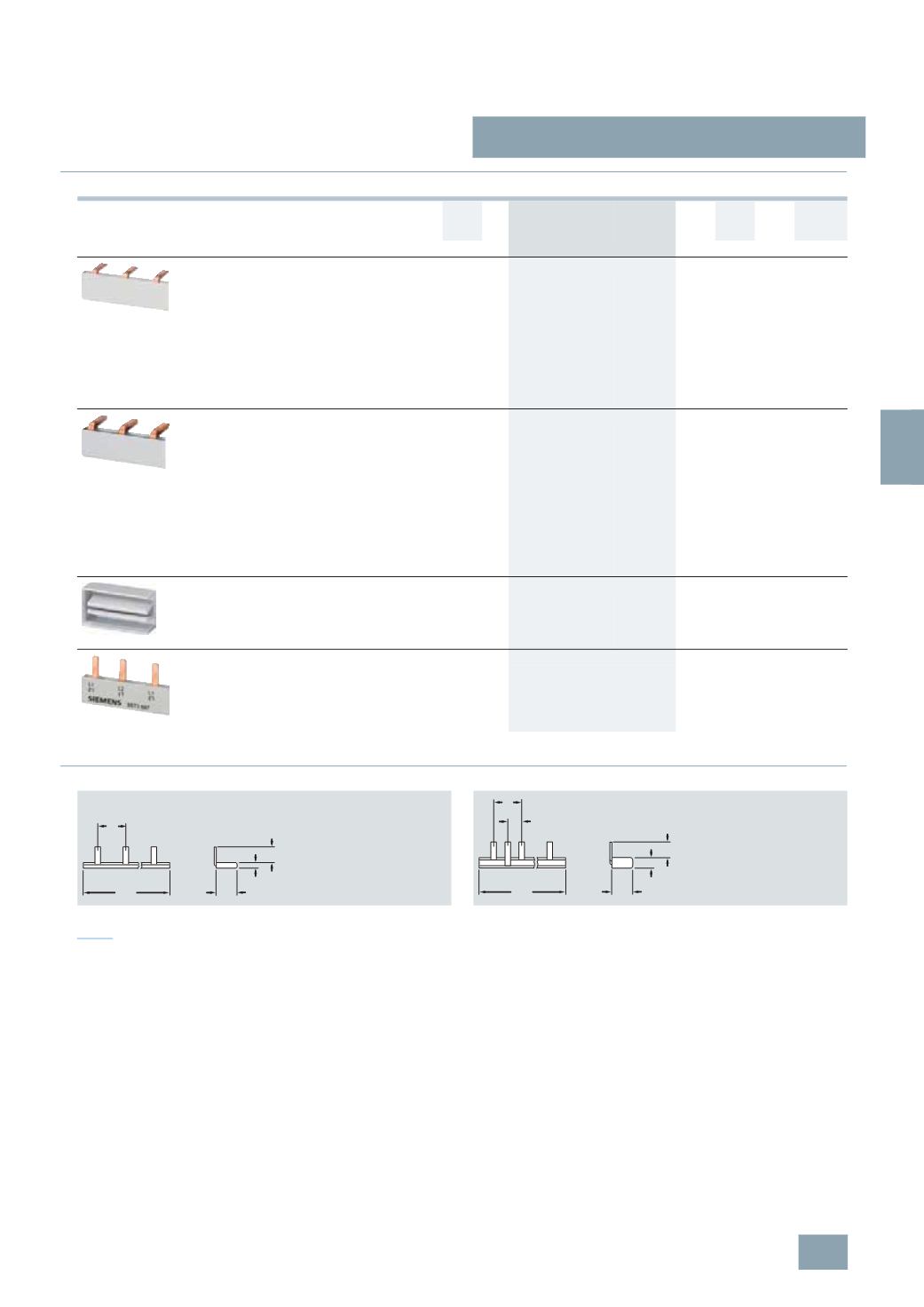
Dimensional drawings
Note:
Pin spacing in MW.
Dimensions of side views in mm (approx.).
Version
Length DT Order No.
Price
per PU
PG PU PS*/
P. unit
Weight
per PU
approx.
mm
Unit(s) Unit(s) kg
Single-phase busbars
For all 5TE8 switches, 20 A and 32 A
In the 12 MW version for the cutting of unused
terminal lugs to ensure insulation clearances if
one device terminal is to be supplied separately
despite being mounted on the busbar,
modular clearance = 1 MW
Infeed of the busbar at the device terminal with
a conductor cross-section of 6 mm
2
to 32 A
Can be mounted top or bottom in the front or
rear terminal area
210
B
5
TE9 100
027 1
10 0.040
Two-phase busbars
For all 5TE8 switches, 20 A and 32 A
In 12 MW version with 1 MW division, whereby
the two busbars are offset by 0.5 MW
Both copper conductors of the two-phase
busbar are insulated together.
Infeed of the busbar at the device terminal with
a conductor cross-section of 6 mm
2
to 32 A
Can be mounted from top or bottom, or in the
front or rear terminal area, thus allowing
realization of a 4-conductor connection using
two two-phase busbars.
220
B
5
TE9 101
027 1
10 0.060
End caps for two-phase busbars
End caps for 5TE9 101 two-phase busbars to
keep insulation clearances when the bar is
being cut.
1
set = 10 units
B
5
TE9 102
027 1
set
1
set
0.001
5
ST3 6 and 5ST3 7 busbar systems
All bars of the 5ST3 6 and 5ST3 7 busbar
systems can also be used for all 1 MW per pole
versions of the 5TE8 switches from 32 A to 125 A
(
see chapter Miniature Circuit Breakers)
.
5
TE9 100
5
TE9 101
14
3,5
10
1
210
I2_13439a
14
6,3
10
1
0,5
220
I2_13440a
© Siemens AG 2008