


 346 / 582

BETA Switching
Switches and Light Indicators
5
TE1 switch disconnectors
7/26
Siemens ET B1 · 10/2008
7
*
You can order this quantity or a multiple thereof.
Version
I
e
U
e
DT Order No.
Price
per PU
PG PU PS*/
P. unit
Weight
per PU
approx.
A AC V AC
Unit(s) Unit(s) kg
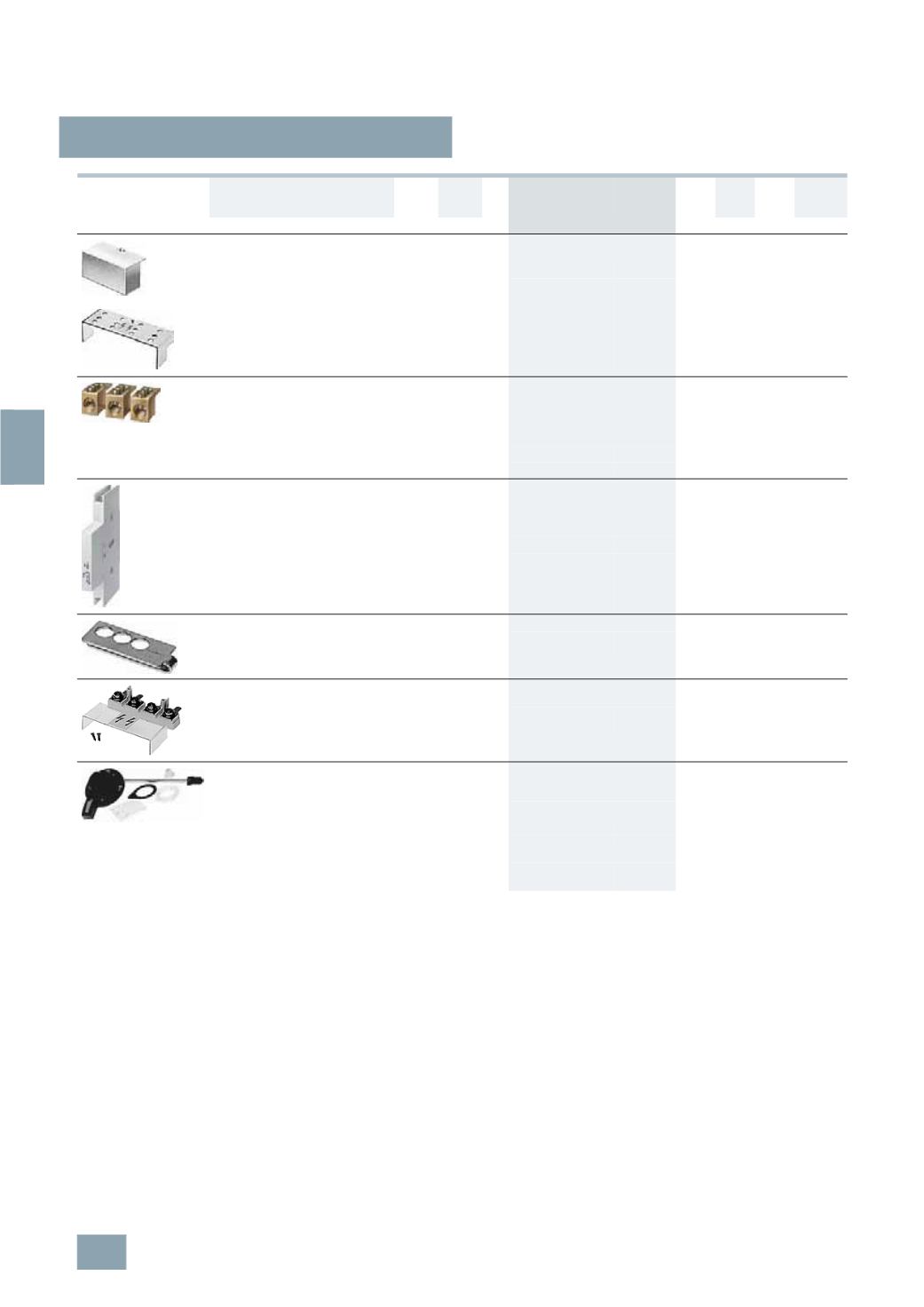
Terminal covers
Sealable
For 100 A and 125 A switch disconnectors
B
5
TE9 000
027 1
1
0.060
For 160 A and 200 A switch disconnectors
B
5
TE9 001
027 1
1
0.050
Cage Clamp terminals
For switch disconnectors 160 A and 200 A,
terminal diameter 14.5 mm for 35 mm
2
cables,
5
mm Allen screw
1
set = 3 units
B
5
TE9 003
027 1
set
1
set
0.080
1
set = 4 units
A
5
TE9 004
027 1
set
1
set
0.080
Auxiliary switches
Can be mounted on the left,
the right or both sides (2 units)
Minimum contact load 24 V, 50 mA
1
CO
6
230
B
5
TE9 005
027 1
1
0.080
2
CO
6
230
B
5
TE9 006
027 1
1
0.080
Locking units
For up to three padlocks
with max. 8 mm
B
5
TE9 014
027 1
1
0.230
Conversion kits, 4-pole, for 100 A and 125 A, for the
connection of busbars or cables with cable lugs
For busbars max. 15 mm wide
Including terminal cover
B
5
TE9 015
027 1
set
1
set
0.110
Rotary actuators with extension axes for
mounting on hinged doors or enclosure
lids, lockable, IP65
Black knob
Axis length 200 mm
B
5
TE9 010
027 1
1
0.550
Axis length 400 mm
B
5
TE9 011
027 1
1
0.550
Red knob
Axis length 200 mm
B
5
TE9 012
027 1
1
0.550
Axis length 400 mm
B
5
TE9 013
027 1
1
0.550
© Siemens AG 2008