


 181 / 582

BETA Protecting
Low-Voltage Fuse Systems
5
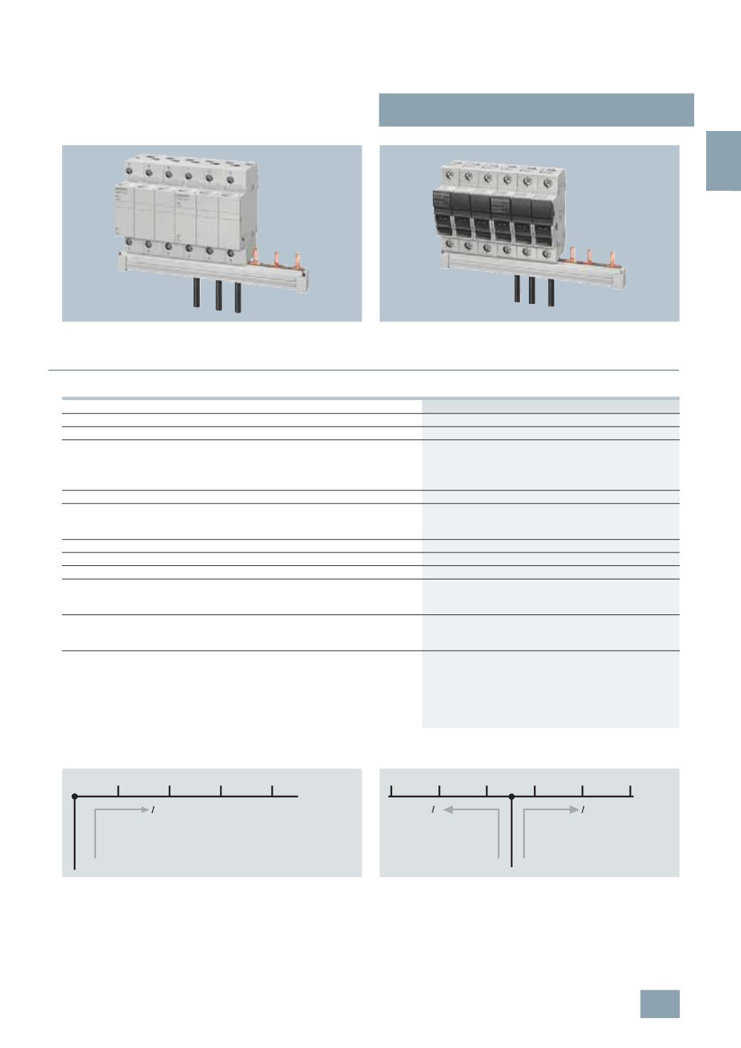
ST2, 5ST3 busbars,
for fuse systems
3/31
Siemens ET B1 · 10/2008
3
*
You can order this quantity or a multiple thereof.
•
Bus-mounting of cylindrical fuse holders 8 x 32 mm and
10
x 38 mm with three-phase pin busbar, which can be cut to
length.
•
Bus-mounting of SITOR cylindrical fuse holders
10
mm × 38 mm
with the same terminal connection as Class CC fuse holder
with three-phase pin busbars, which can be cut to length.
■
Technical specifications
Infeed at the start of the busbar
Infeed along the busbar or midpoint infeed
5
ST, 5SH
Standards
EN 60439-1 (VDE 0660-500): 2005-01
Busbar material
SF-Cu F 24
Partition material
Plastic, Cycoloy 3600
heat-resistant to more than 90 °C
flame-retardant and
self-extinguishing,
dioxin and halogen-free
Rated operational voltage U
c
V AC 400
Rated current
I
n
•
Cross-section 10 mm
2
A
63
•
Cross-section 16 mm
2
A
80
Rated impulse withstand voltage U
imp
kV
4
Test pulse voltage (1.2/50)
kV
6.2
Rated conditional short-circuit current
I
cc
kA
25
Resistance to climate
•
Constant atmosphere
Acc.to DIN 50015
23/83; 40/92; 55/20
•
Humid heat
Acc. to IEC 60068-2-30
28
cycles
Insulation coordination
•
Overvoltage category
III
•
Degree of pollution
2
Maximum busbar current
I
S
/
phase
•
Infeed at the start of the busbar
-
Cross-section 10 mm
2
A
63
-
Cross-section 16 mm
2
A
80
•
Infeed at the center of the busbar
-
Cross-section 10 mm
2
A
100
-
Cross-section 16 mm
2
A
130
The sum of the output current per branch must not be greater than the
busbar current
I
S1.2
/
phase.
S
I2_13755
S1
S2
3
2
1
1
2
3
I2_13754
© Siemens AG 2008