


 184 / 582

BETA Protecting
Low-Voltage Fuse Systems
5
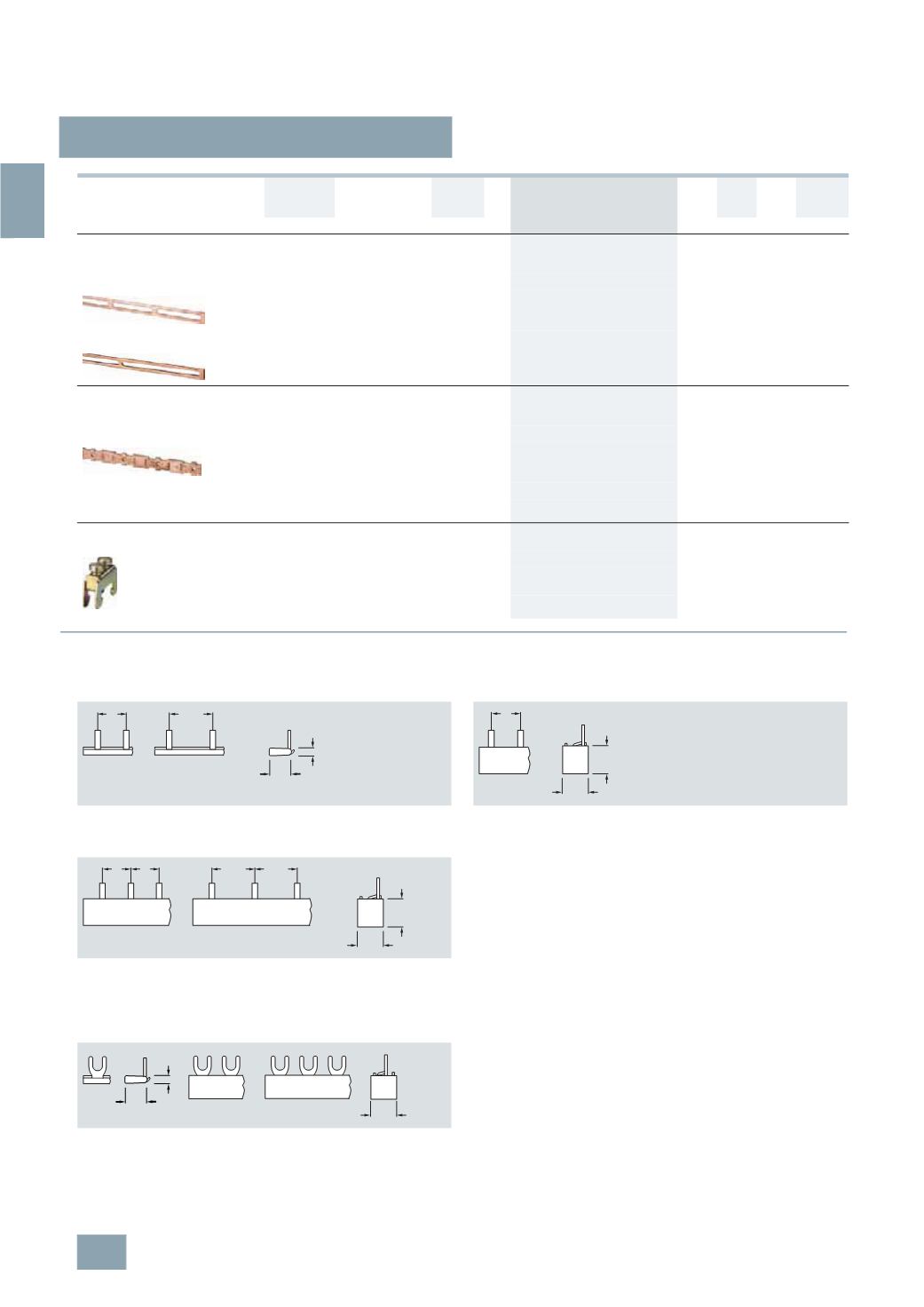
ST2, 5ST3 busbars,
for fuse systems
3/34
Siemens ET B1 · 10/2008
3
*
You can order this quantity or a multiple thereof.
■
Dimensional drawings
Phases Conductor
cross-section
Load capacity
up to
Length DT Order No.
Price
per PU
PG PU PS*/
P. unit
Weight
per PU
approx.
mm
2
A
mm
Unit(s) Unit(s) kg
Busbars
for 1-pole DIAZED fuse bases made of ceramic
with terminal versions BB and BS
Size DII, for 19 bases
Single-
phase
24
80
1000
A
5
SH3 500
016 1
1/25 0.095
Size DIII, for 25 bases
Single-
phase
39
120
1000
A
5
SH3 501
016 1
1/25 0.180
Busbars
For DIAZED bus-mounting bases/EZR
with thread for screw adapters
For size DII, 42 5SF6 005 bases
Single-
phase
48
150
2000
C
5
SH3 54
016 1
5
0.740
For size DIII, 34 5SF6 205 bases
Single-
phase
48
150
2000
C
5
SH3 55
016 1
5
0.740
Bus-mounting terminals
For DIAZED EZR bus-mounting bases
Non-insulated
For con-
ductors
1.5 ... 16
A
8
JH4 122
046 1
10 0.012
For con-
ductors
10 ... 35
A
8
JH4 124
046 1
10 0.024
5
ST3 7
Pin spacing in MW
Dimensions of side views in mm (approx.)
5
ST3 700
5
ST3 701
5
ST3 703
5
ST3 704
5
ST3 705
Single-phase Single-phase
5
ST3 708
5
ST3 710
5
ST3 714
5
ST2
Fork spacing in MW
Dimensions of side views in mm (approx.)
5
ST2 186
5
ST2 190
5
ST2 187
5
ST2 188
5
ST2 191
5
ST2 192
3,5
13
1,5
I2_13674
1
15
18
1
L1 L2
I2_13748
15
18
L1 L2 L3
1 1
L1
L2
L3
1,5 1,5
I2_136749
15,1
3,5
13
I2_13750
© Siemens AG 2008