


 183 / 582

BETA Protecting
Low-Voltage Fuse Systems
5
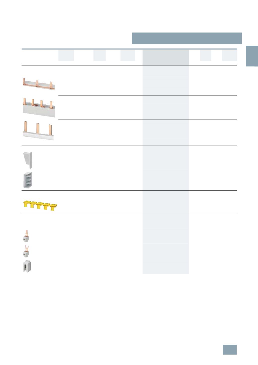
ST2, 5ST3 busbars,
for fuse systems
3/33
Siemens ET B1 · 10/2008
3
*
You can order this quantity or a multiple thereof.
Phases Conductor
cross-section
Load
capac-
ity up to
Pin
spacing
Length DT Order No.
Price
per PU
PG PU PS*/
P. unit
Weight
per PU
approx.
mm
2
A
MW mm
Unit(s) Unit(s) kg
For cylindrical fuse holders 8 × 32 mm and 10 × 38 mm
For SITOR cylindrical fuse holders 10 × 38 mm
For Class CC fuse holders
Can be cut to length, without end caps
Single-
phase
16
120 1
1016
A
5
ST3 701
027 1
1
0.190
Two-
phase
120 1
A
5
ST3 705
027 1
1
0.290
Three-
phase
16
120 1
1016
}
5
ST3 710
027 1
1
0.430
Cannot be cut to length, fully insulated
Single-
phase
16
1
214
}
5
ST3 700
027 1
1
0.040
Two-
phase
1
A
5
ST3 704
027 1
1
0.060
Three-
phase
1
}
5
ST3 708
027 1
1
0.100
End caps for busbars
For single-phase 5ST3 7, 5SH5 5 busbars 156
}
5
ST3 748
027 1
10 0.001
For three-phase 5ST3 7 and 5SH5 320 busbars
}
5
ST3 750
027 1
10 0.001
Touch protection for free connection
of pin busbars
Yellow, (RAL 1004)
A
5
ST3 655
027 1
10 0.003
Terminals
For NEOZED fuse bases D01/D02 made of ceramic
For DIAZED fuse bases DII/DIII, made of ceramic
For cylindrical fuse holders
Terminal version S
For con-
ductors
2 ... 25
}
5
SH5 327
016 1
10/300 0.014
Terminal versions B and K
For con-
ductors
6 ... 25
}
5
SH5 328
016 1
10/300 0.014
For the infeed of fork-type or pin busbars
For con-
ductors
6 ... 35
A
5
ST2 157
027 1
5
0.030
© Siemens AG 2008